Creating a Sequential Groove Operation with the Legacy Interface | ||
| ||
-
From the
Axial Machining section, select Sequential
Groove
 then a position in the Manufacturing Program.
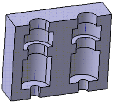
A typical part to machine with two grooves looks like this:

- A Sequential Groove entity is added to the Manufacturing Program.
- The Sequential Groove dialog box opens directly at
the Geometry tab
 . This
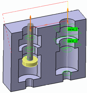
tab includes a sensitive icon to help you specify the geometry.
 - Areas colored red, texts such as No point and No geometrical feature has been selected indicated that geometry is required.
-
Still in the Geometry tab which comprises a
Global and a Local tab:
-
In the Global tab, select the red groove depth
representation then select the two holes.
See Selecting Geometry for more information.
The sensitive icon is updated with information such as the number of machining points, the depth and diameter of the first selected hole, ...
- Set Number of Levels to 2.
-
In the Local tab, select the plane representations
in the sensitive icon, and the desired planes in the part.
Plane 1 is the plane of the first groove in the part, plane 2 is the plane of the second groove.

- Optional: Select the axis representation in the sensitive icon to invert the tool axis direction.
- Optional: Select the check boxes below the sensitive icon to modify the corresponding data.
-
In the Global tab, select the red groove depth
representation then select the two holes.
-
Select the Motions tab in the
Strategy tab
 and define the
required motions.
- Click the icon corresponding to the required motion.
- Select values from the lists, or key in the values.
- Click OK to add the motion.
For example:
Rank Name Plane number Compensation Feed Rate Appl. Mode 1 Go To Plane.1 
1 2 50mm_mn - 2 Circular.1 
- - Machining - 3 Go To Plane.2 
2 1 50mm_mn - 4 Circular.2 
- - Machining - 5 Go To Clearance.1 
- 1 50mm_mn Last Level The motions are added and listed in the dialog box. -
Select the Tool tab
 and choose a tool, example, a T-slotter tool with a
nominal diameter lower than that of the top hole.
Drill, multi diameter drill, spot drill, center drill, countersink, tap, two sides chamfering, boring and chamfering, boring bar, reamer, T-slotter, end mill, face mill, thread mill, conical mill and counterbore mill tools are supported.
See Assigning a Tool Element to a Machining Operation.
- Click More >> and select the Compensation tab to specify a second corrector.
-
Select the Feeds and Speeds tab
 to specify the
feedrates and spindle speeds for the operation.
-
Select the Macros tab
 to specify the
desired transition paths.
-
Click Display or
Simulate to check the validity of the operation.
- The tool path is computed.
- A progress indicator is displayed.
- You can cancel the tool path computation at any moment before 100% completion.

- Click OK to create the operation.