Defining an Electrostatic Paint Profile | |||||
|
| ||||
-
From the Surface section of the action bar, click select Paint
Profile
 .
You are prompted to select a robot.
 -
In the work area,
select the robot that will perform the paint action.
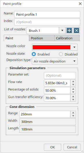
The Paint profile dialog box appears.
- Optional:
You can enter a Name and specify an Index
for the new profile.

-
Select a brush from the List of nozzles.

Click
 to add a new brush to define, or
  to delete the current brush.
 -
In the Paint tab, specify a paint color from the
Nozzle color list.
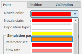
Several nozzles can be associated to a robot, and each can be activated or deactivated per profile. Nozzle state allows you to specify whether the selected nozzle for the current profile is Enabled (paint is deposited) or Disabled (no paint is processed).

Deposition type allows you to select from two types of paint deposition.
- Air nozzle deposition sprays paint from the gun and is deposited from the sole action of the spray.
- Electrostatic rotating bell sprays paint from the gun and paint particles are attracted electrostatically by an electrolytically-processed paint surface.

Select Electrostatic rotating bell.
-
In the Simulation parameters section:
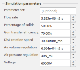
- Optional: Parameter set is used to specify an integer to identify the parameters, and is used for download/upload with Robot Programming.
- Flow rate specifies the amount of paint dispatched for a given time period.
- Percentage of solids specifies the percentage of the total paint volume that is due to paint solids.
- Gun transfer efficiency specifies the percentage of sprayed paint solids that will adhere to the surface.
- Disk rotation speed specifies the current speed of rotation for the bell cup atomizer.
- Air volume regulation specifies the current flow rate of the shaping air in the ERB paint gun.
- Air pressure regulation specifies the current pressure of the shaping air.
- Voltage specifies the electrostatic voltage applied to the ERB paint gun at the current simulation time.
-
In the Cone dimension section:
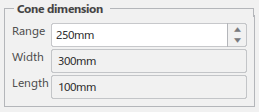
- Range specifies a distance from the nozzle beyond which paint will not adhere to the surface.
- Width is computed from the current flow rate film build deposition along X, as defined in the Calibration tab, and represents the width of the base of the cone.
- Length is computed from the current flow rate film build deposition along Y, as defined in the Calibration tab, and represents the length of the base of the cone.
-
Click the Position tab.
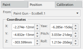
- In the From list, select a tool profile that the nozzle position will be positioned relative to.
- In the Coordinates section, define X, Y, Z, Yaw, Pitch, and Roll offsets relative to the current TCP position.
-
Click the Calibration tab and define the Experiment
parameters.
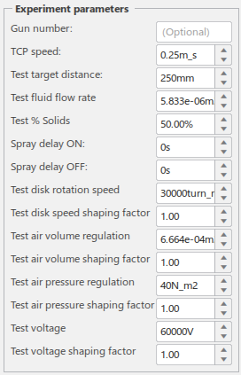
- Optional: Gun number specifies the gun number as referenced by the robot program and is used by upload/download.
- TCP speed specifies the speed at which the TCP is traveling during the experiment.
- Test target distance specifies a fixed distance between the gun nozzle and the surface being painted.
- Test fluid flow rate specifies the rate of fluid through the nozzle during the experiment.
- Test % Solids specifies the percentage of total paint volume that is due to solids during the experiment.
- Spray delay ON: specifies a time delay in spray deposition after paint flow is turned on.
- Spray delay OFF: specifies a time delay in spray deposition after paint flow is turned off.
- Test disk rotation speed specifies the rotation speed for the bell cup disk atomizer during experiment.
- Test disk speed shaping factor specifies a factor to control the extent of the spray width due to an increase in rotation speed.
- Test air volume regulation specifes the flow rate of the shaping regulation air during the experiment.
- Test air volume shaping factor specifies a factor to control the extent of the spray width due to an increase in regulation air volume.
- Test air pressure regulation specifies the pressure of the shaping regulation air during the experiment.
- Test air pressure shaping factor specifies a factor to control the extent of the spray width due to an increase in air pressure.
- Test voltage specifies the electrostatic voltage applied during the experiment.
- Test voltage shaping factor specifies a factor to control the extent of the spray width due to an increase in electorstatic voltage.
-
Film deposition displays deposition values measure along the X
or Y axis of the cone.
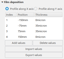
- Each Index value provides a Thickness measurement at the specified Position.
- Click Add Values to add another value below the current selected index.
- Click Delete Values to remove the currently selected index.
- Import Values allows you to import a set of position-deposition values from an external file. Existing values are removed and replaced at the time of import. The imported file must contain four columns of at least two values.
- Export Values exports a set of position-deposition values to an external file.
- Position and Thickness allow you to edit the current respective values of the selected index.
-
In the Paint Profile dialog box, click OK
to create the profile.
The new profile appears in the Profiles side tab of the browser.
