Creating a Surface Sequence | ||||||
|
| |||||
-
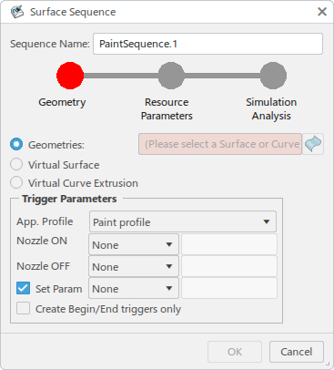
From the Teach context toolbar, click Insert a Paint Sequence
 .
.
The Surface Sequence panel appears, and you are prompted to select a surface.
-
In the work area,
select a surface to paint.
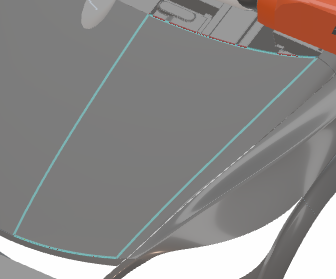
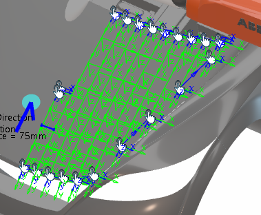
Upon selection, the trajectory preview appears on the surface.
-
In the Surface Sequence panel, click Add/remove
geometries to generate surface path
 to select additional surfaces for the trajectory.
The path preview becomes hidden, and you can select surfaces in the work area to add or remove them from the Geometries list as required.

A context toolbar appears and provides commands for the following functions:

Reset selection removes any selections you have made since starting the Add/remove geometries to generate surface path command. 
Toggles between Single surface selection (only the selected surface is selected) and Automatic adjacent surface selection (surfaces adjacent to the selected surface are also automatically selected). 
When selected, Body Normals are indicated by an arrow pointing from the selected surface. You can click on the displayed body normal to reverse its direction. 
Click Select mask surface(s) or closed curve(s) to select surfaces that will act as a mask as described in Generate a Path Within a Defined Boundary. 
Exit ends the Add/remove geometries to generate surface path command. Click Exit
when all
necessary selections have been made and return to the Surface
Sequence dialog box. -
In the Path tab, define the following options:
-
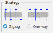
Strategy specifies whether the trajectory is traversed with
alternate strokes in opposite directions (Zigzag) or with all
strokes in the same direction (One-way).
-
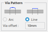
Via Pattern specifies whether the approach and depart point
of two consecutive strokes are connected with an additional via point
(Arc). The additional via point is offset from the
Approach/Departure points by the value specified in Via Offset.
When Line selected, no additional point is created.
-
Distance between Strokes specifies either a
Constant or Variable distance between
strokes. When Variable is selected, the distance between
strokes can be changed by either selecting a stroke in the work area
and using the manipulator, or using the Distance to Next Stroke
in the Stroke tab.

-
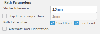
In the Path Parameters section, Stroke
Tolerance specifies a value used to determine where tag points are
generated along the selected surface. Lower values result in a higher number of points
generated and higher accuracy. You can select Skip Holes Larger
Than and enter a hole size to be skipped. Path
Extremeties allows you to create a Start Point
and End Point at the beginning and end of the sequence,
respectively. When selected, Alternate Tool Orientation flips
the robot tool orientation at the beginning of every other stroke of the
sequence.
-
Reposition allows you to reorient and/or reposition the
entire sequence using the orientation Robot. A context menu appears that allows you to apply or undo modifications and return
to the Surface Sequence dialog box.

-
Strategy specifies whether the trajectory is traversed with
alternate strokes in opposite directions (Zigzag) or with all
strokes in the same direction (One-way).
-
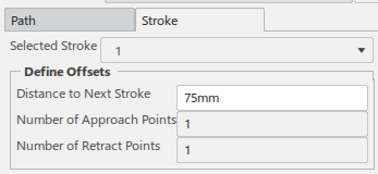
In the Stroke tab, Selected Stroke
displays the list of individual strokes for selection when Distance between
Strokes is set to Variable in the
Path tab. When a stroke is selected, it is displayed in blue in
the work area. You can specify the Distance to Next Stroke and
Number of Approach Points and Number of Retract
Points in the selected stroke.
-
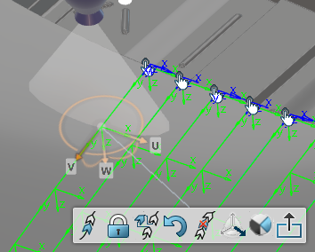
Click any point in the trajectory to access a context toolbar providing the following commands.

Inserts a new point before the selected point in the trajctory. 
Toggles between locking and unlocking the selected point. 
Inserts a new via point after the selected point. 
Reverts changes made to the selected point. 
Deletes the selected point. 
Toggles between editing all axes of the selected point, or only the stroke direction axis. 
Toggles between showing and hiding the reach disc for the selected point. Exits the target manipulation mode. 
-
List of points provides a list of all of the points included in
the trajectory, and indicates the Type of each point. Select a
point in the list to move the robot TCP to that point and access the commands in the above
context toolbar.
-
In the Surface Sequence dialog box, click Resource
Parameters.
The Robot tab lists any Triggers that have been defined.

Click the Conveyor tab to view and define Trolley information if a conveyor is defined in your current scenario.

Current Tracking Profile lists the available tracking profiles that have been defined for the robot.
Current Trolley lists available trolleys to place along the conveyor.
Speed specifies the rate at which the trolly moves.
Positioning provides parameters to define the position of the trolley.
-
Click Simulation Analysis to display the
Player
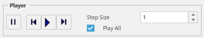
.The Player allows you to simulate the previewed trajectory based on the current settings of the Surface Sequence dialog box.
Pause stops the simulation at the current instruction. 
Play Previous moves to the previous operation in the sequence. 
Play Selection plays the entire sequence of operations of the task from beginning to end. 
Play Next moves to the next operation in the sequence. Step Size You can step forward based on the specified step size. Play All When selected, plays all of the instructions of the current task. -
Click OK to create the surface sequence.
The new sequence appears in the Teach panel.
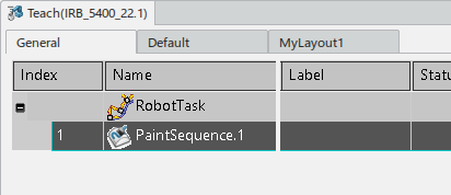
-
In the Teach panel, select the sequence and click
Expand the multi motion sequence
 .
.
The Multi Motion Editor panel appears and presents an ordered list of the individual instructions of the sequence, with the selected paint sequence as the root node.

You can insert new instructions, modify the motion parameters of the existing instructions, and delete instructions from the sequence with the commands provided in the Teach context toolbar.
-
Click Edit Surface Sequence
 to
temporarily hide the Teach environment and return to the Surface
Sequence dialog box. Click OK or
Cancel in the dialog box to return to the Teach
environment.
to
temporarily hide the Teach environment and return to the Surface
Sequence dialog box. Click OK or
Cancel in the dialog box to return to the Teach
environment.