About Allocation and Preallocation

You can define the mapping or only a preallocation between a topology and either a function or a software component.

This page discusses:

Allocation Processes

Using the System tab, you can define the mapping between a function or a software component and hardware (EE components) architecture using a system mapping.

Functional Allocation Process

The complete process is the following:

  1. Map the functional onto hardware. For more information, see Allocating a Function to an EE Component.
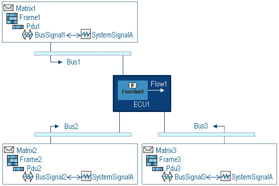
  2. Allocate the functional flows between EE components (resulting from the function allocation to the EE channels: WiredLink, communication buses...). For this, the following steps are required:

    1. Map hardware onto communication.

      Associate system signals to the EE channel:

    2. Map functional data onto communication.

Software Allocation Process

The complete process is the following:

  1. Map the software onto hardware. For more information, see Allocating a Software Component to an EE Component.
  2. Allocate the software between EE components (resulting from the software allocation to the EE channels: WiredLink, communication buses...). For this, the following steps are required:
    1. Map hardware onto communication.

      Associate system signals to the EE channel:

    2. Map software data onto communication.

Allocation of Connection on Wire

You can use a wire or a generic wire as an interface to allocate a flow or a signal in your system mappings.

The interface connects two I/O hardware ports of hardware components. When mapping a flow or a signal to a generic wire, you need to specify a subwire of the generic wire.

In a wire mapping of a generic wire, you can select ports and subwires (subports) of compatible types bearing the same name. You can associate one producer with N consumers.

In the functional case, if you allocate a connection on a wire, you associate:

  • Two functional ports with a system signal.
  • A wire with a system signal.
    Note: If it is a generic wire, you also select a subport for each concerned hardware port.

In the software case, if you allocate a connection on a wire, you associate:

  • Two software ports and one data element with a system signal.
  • A wire with a system signal.
    Note: If it is a generic wire, you also select a subport for each concerned hardware port.

Preallocation

In most cases, you can directly create a mapping of functional flows or of data elements to channels. However, when the path used by the data to transit is only known, you need to create a preallocation.

The data corresponding to this use case is the following:

  • New data when the signal does not yet exist.
  • Data coming from another domain and the signal to use is not known.

The scenario describing the functional case also works for the software case.

For this preallocation, you map functional flows onto channels without associating a system signal. The preallocation is also named signal path constraint.

You can then assign the signal as soon you know the signal and how it transits to end the mapping.

Difference Between Allocating to Bus Signal or to System Signal

You can either allocate to a bus signal or to a system signal.

The following explanation describes the process for a functional allocation. The process is identical for a software allocation.

In the example, the function is allocated with an EE component connected to several buses with a communication matrix referencing the same system signal: SystemSignal.

Allocation to Bus Signal

If you select Choose system signal by selecting bus or wire mappings to allocate the flow to the BusSignal1, the result is the following:


You precisely define which bus is concerned by the information transmission.

Allocation to System Signal

If you do not select Choose system signal by selecting bus or wire mappings to allocate the flow to the SystemSignal, the result is the following:


The information is transmitted through all the buses, which referenced the chosen system signal.