-
From the Diagrams section of the action bar,
click Show Virtual Link Routes
 .
.
A dialog box appears. It lists the following elements:
- The list of private virtual links for the topology associated with the active
diagram.
- The shared virtual links defined in the parent topology, if the topology is a
subsystem.
-
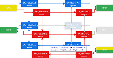
Select virtual links to highlight their routings.
The current diagram switches into read-only.
All the network elements involved in a routing are highlighted.
- Switches and Ethernet segments are displayed in the same color.
Note:
Depending on the number of networks, the colors are as follows:
- For two networks: red and blue
- For more than two networks: red, blue, and other
- In the case of private virtual links:
- The ECU entry is displayed in yellow.
- All the ECU exits are displayed in green.
- In the case of shared virtual links:
- The input delegation port is displayed in yellow.
- All the output delegation ports are displayed in green.
- Oriented arrows show the direction of the virtual links.
Note:
If an ECU or a delegation port is simultaneously an entry
and an exit, it is displayed with yellow and green.
Consequently, all entries, switches, Ethernet segments, and exists which are not
concerned by the selection appear in gray.
-
Optional: Hover over Ethernet segments to display associated virtual
links.
The virtual link or the multiple virtual links routed on each segment appear in
notes.
-
From the Diagrams section of the action bar,
click Hide Virtual Link Routes
 to
cancel the virtual link routing display and switch to edit mode.
Example
For the following topology with private
virtual links, the routing is displayed below.


