Browsing, Editing and Creating Electrical Physical Data via the Spreadsheet

You can browse, edit and create objects (instances, ports) via the Spreadsheet. You can also create an electrical link between an electrical physical system and an electrical geometry via the Spreadsheet.

Note: Electrical features with no geometrical representation i.e. conductors and conductor groups are supported by the Spreadsheet: you can browse, create and edit them in the Spreadsheet. Electrical features with geometrical representation i.e. protective coverings, branches and segments are supported by the Spreadsheet: you can browse and edit them in the Spreadsheet but you cannot create them. For more information, see About Electrical Physical Entities Browsed, Created and Edited by the Spreadsheet.

This task shows you how to:


Before you begin: Create an electrical product containing an electrical geometry, an electrical physical system and a connector.

Browse Electrical Data

You can scan and navigate through the electrical data within the Spreadsheet.

  1. From the standard area of the action bar, click Spreadsheet .
    In the Spreadsheet, you can:
    • Browse the product structure loaded in session
    • Filter entities
    • Edit their properties (edition in mass is possible)
    • Create new data (creation in mass is also possible).
    Note: For more information, see About the Spreadsheet.
  2. Click Expand All Rows
    All the elements (instances and publications) under the root product are shown in the Spreadsheet. The elements present in your model are identical to those in the Spreadsheet.

  3. Select the electrical geometry in the Spreadsheet.
    The selection of any element in either of the windows highlights the element in the other window.

Edit Electrical Data

You can edit the attributes of the electrical objects in the Spreadsheet.

  1. Select the electrical geometry and click Display Additional Properties .
    A dialog box appears and you can edit the Value boxes. See Editing Properties in the Spreadsheet.
    Note: You can choose which attributes to be shown in the main Spreadsheet as a column, for this you can right-click a column header and select or deselect the column(s) you want to display.
  2. Close the window.
  3. Select the row of the object in the Spreadsheet and edit a property.
    The modification is visible in both windows.
  4. Multi-select several cavities and edit the Extra Length of one of them.


    The modification is reported on all the selected cavities.

    Note: Electrical features with geometrical representation i.e. protective coverings, branches and segments can be edited in the Spreadsheet. These changes are updated in the Feature Properties in your 3D content.

Create New Electrical Data

You can create electrical types of physical objects in session using the Spreadsheet.

  1. Select the electrical geometry (GBN2) and click New Child .
    A new row appears under GBN2.

  2. Click the row to select a Type.
    The electrical object names are displayed.

    All the devices have the same icons in the list, but once a device is instantiated in the structure, it has its specific icon. The new object is automatically inserted in the structure.

    Notes:
    • The visible types are the possible types that can be aggregated by this existing component.
    • Mass creation of a specific electrical type is possible.
    • Electrical features with no geometrical representation i.e. conductors and conductor groups can be created via the Spreadsheet. For this, select an electrical physical system representation and click New Child, a sub-menu is displayed and you can select Conductor or Conductor Group:You can also edit them.
  3. Edit the product's name in the Spreadsheet view.
    The product present in the work area gets the same name.
  4. Select the SIC (SIC12) and click New Child four times to create four rows under the SIC.
  5. Multi-select these new rows and edit the Type of one row.
    A drop-down list appears of the possible entities that can be inserted under the SIC.
  6. Select the Port type.
    Four rows of Port type are created under the SIC.

Duplicate Data

You can duplicate entities (except Ports) in the Spreadsheet.

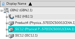
Select a SIC (SIC12) and click Duplicate Row
Another instance of the same reference is created at the same level:
Associate an Electrical Physical System with an Electrical Geometry

You can create an electrical link between an electrical physical system and one or several electrical geometries via the Spreadsheet.

  1. Select the Properties contextual command of the electrical physical system in the work area.
    This dialog box contains the following information:
    • Type: Electrical Physical System.
    • SubType: Unset.
    • Associated Electrical Geometry: There is no Electrical Geometry associated with this electrical physical system.

      The electrical physical system has no electrical links.

  2. Click the Associated Electrical Geometry(s) attribute in the Spreadsheet.
    A list is displayed, but in our example it is empty because the electrical physical system is not connected.
  3. Press the Add Value button to add an electrical geometry to the list and select an electrical geometry in the Spreadsheet View. See Creating an Object in the Spreadsheet.
    The electrical physical system is linked to the electrical geometry present in the list. You can check the information by clicking the Properties contextual command of the electrical physical system in the work area:
    • Type: Electrical Physical System.
    • SubType: Unset.
    • Associated Electrical Geometry: GBN2

      The electrical physical system has electrical links.

    Note: When there are more than one electrical geometry linked to the electrical physical system, its Associated Electrical Geometry(s) cell displays the "Multiple" value.
  4. To remove an electrical geometry from the Associated Electrical Geometry(s) list, click .

Connect Devices

In the Spreadsheet, the Connected Device column displays connectivity information for connection points. It also allows you to edit or delete an existing engineering connection.

  1. Display a root product in the Spreadsheet.

    The connectivity of devices is displayed in the Connected Device column. In our example:

    • EQT.1 is connected to SIC1.1 through the connection point CavityCnctPt.1 (in blue). EQT.1 is the primary device of this engineering connection and SIC1.1 is the secondary device.
    • EQT2.1 is connected to SIC2.1 through the connection point CavityCnctPt.1 (in green). EQT2.1 is the primary device of this engineering connection and SIC2.1 is the secondary device.

  2. Click the cell of a connected connection point.
    1. To edit the engineering connection, click another connection point cell.

      A connection point is compatible if:

      • It is not already connected to another device.
      • It has the same type (Standard or Advance) as the first selected connection point.
      • Primary and secondary devices can be connected together. For more information, see Connectable Devices Reference Table.

    2. To remove the engineering connection, press Delete.

Note: Device connectivity can be managed in the Floating Spreadsheet and the connectivity information is available when you export a spreadsheet.