Insert an Electrical Branch Geometry
-
From the Branch section of the action bar, click Electrical Branch Geometry
 . .
The Electrical Branch Geometry dialog box
appears.
-
In the Electrical Branch Geometry tab, define the
following electrical properties:
- Sub-type
- Separation Code
Note:
If you specify
this attribute, the new branches added under the electrical branch
geometry inherit the same separation code. However, if you modify
the separation code defined on the electrical branch geometry,
the property is not updated for your branches.
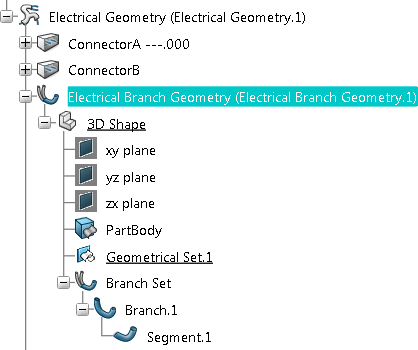
The electrical branch geometry is inserted and the
Branch Definition dialog box appears. you can specify the
parameters of the first branch. Note:
The electrical branch geometry
is a 3D Part (Part Number,
Description, etc. defined in the 3D Part tab), that is to
say an object composed of a product with a 3D Representation. Its main
characteristic is to have a "Terminal node" behavior and the impossibility to
delete the link between the Product and the Representation; the 3D Shape is a
mandatory representation. The electrical branch geometry will then inherit
the 3D Part's properties such as deleting, duplicating, versioning, changing
maturity. A 3D Part is also seen as one object in the
Save and Search in Database
dialog boxes. The next tab of the dialog box lets you manage
attributes of the associated representation.
Define the Parameters of the First Branch
-
In the Branch Definition dialog box, define the
following parameters:
-
Specify the diameter or the section:
-
Enter a value in the Diameter box and have
the section computed automatically. Or,
-
Enter the Section and have the diameter
computed automatically.
-
In the Bend Radius
box, enter the bend radius value.
The bend radius is the minimum bend radius allowed for the whole segment.
A bend radius at least equal to the diameter is recommended to avoid tight turns. A message
appears when the bend radius is smaller than the diameter because the branch
route may be unavailable.
-
Enter a value in the Bend Radius box.
Or,
-
Select the Bend Radius Ratio check box then
specify a factor, and have the bend radius computed. The factor is
multiplied by the diameter to determine the minimum bend radius.
The bend radius entered is used as an input.
In Standard algorithm mode, you can have the
system optimize the
bend radius to keep the flexible curve.
The Computed bend radius is displayed when you
have routed the branch. Status lights show whether or not the computed
bend radius respects the minimum bend radius entered.
-
Select the Build
Mode, for example Slack and enter a
percentage. In the Build Mode list, select one of the
options:
- Slack:
Segment length is the minimum length increased by a user-defined percent
entered in the Slack(%) box. The
Length box is unavailable.
- Length: Segment
length is defined by the user in the Length box.
The Slack(%) box is unavailable.
- Bend: Segment
length corresponds to the minimum computed length between the points
defining the segment route. Slack(%)
and Length boxes are
unavailable.
- Straight bend: Segment length corresponds to
the path defined by arcs of circles of fixed radius and straight lines
going through points. You can add a tangency to each point in the
Route Definition dialog box to manage the route
direction of the curve. Slack(%) and
Length boxes are unavailable.
- Constrained length: this mode is available
only if you have activated the FLEX algorithm via
and if you have already routed the branch before. By
default the original length of the branch is kept.
Slack(%) and Length
boxes are unavailable.
- Cornered Polyline: Segment length corresponds
to the shortest path defined by arcs of circles of fixed radius and
lines. The curve does not go through the points, except if the bend
radius is equal to zero. Tangency at route points is ignored.
Slack(%) and Length
boxes are unavailable.
Notes:
- If you select the following parameters in the
Branch Definition dialog box:
- Bend Radius for check > Bend
Radius: 2mm for
example,
- Build Mode > Mode:
Cornered Polyline,
- Click Route Definition and
select the Route elements. Click
OK,
- Click Segments Definition to
choose rectangular profile type. Click
OK,
the curves of the branch have the following shape:
- If you follow the same steps as above but you set the bend
radius as 0, the branch has cornered angles because all its
curves are created with zero bend radius:
- You can transit from the Cornered
Polyline to a non-cornered polyline mode
(Slack,
Length,
Bend, Straight
Bend) and vice-versa. And the branch shapes
generated via Build Mode respect the
respective algorithm. Note that tangency at route points is
not considered in computation, hence all the tangents
applied to route points, except for devices with their own
tangency, will be lost and can never be retained (red arrows
for Tangent / Direction selection on routed points will not
be visible, except for devices and supports).
- You can route a branch, the curve of which has a
Build Mode set to Cornered
Polyline.
- When the Bend Radius is equal to
zero, it is not allowed to change the Build
Mode from the Cornered
Polyline to a non-cornered polyline mode. A
message is displayed asking you to give the Bend
Radius a non-zero value before changing the
Build Mode.
At this stage, segment parameters are defined. You now route the segment
to complete the definition and create the geometrical representation of
the flexible curve. Note:
Canceling the branch definition before routing
creates a branch set,
branch and segment in the tree; no geometry, however, is
defined.
-
Click Route Definition and route the branch.
-
Click OK in the Route
Definition dialog box when done.
-
Click OK in the Branch
Definition dialog box.
The Electrical 3D Design
app switches to the Electrical 3D Part Design
app (representation context). An
electrical branch geometry comprising one branch and one segment is
created by default.
-
Click OK in the Branch
Definition dialog box when done.
The first branch is fully defined with associated geometry and
route. The flexible curve is visible in the geometry area.
You are now able to route branches or
modify segments.
|

