-
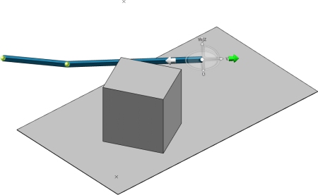
In the 3D area, select a route element.
- The
Manual Routing Mode
 is activated.
 - The Robot is snapped to the selected element.
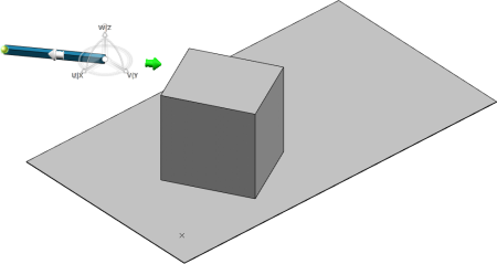
- Optional:
Edit the default orientation of the Robot.
For more information, see About the Robot Orientation.
-
From the Branch Properties panel, hover over the
Context-based Routing Assistant icon
 , and then select one of Robot's axis:
| Option | Description |
|---|
 | Sets the U axis as the preferred routing direction. |
|---|
 | Sets the V axis as the preferred routing direction. |
|---|
 | Sets the W axis as the preferred routing direction. |
|---|
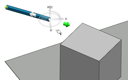
In our example, the orientation of the
Robot is edited and the V axis is selected as the preferred
routing direction.
-
Hover over a geometric element.
In our example, a planar surface is hovered.
A blue bullet displays the intersection between the axis vector and the plane.
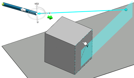
- Click the geometric element.
The passing point is created at the intersection.
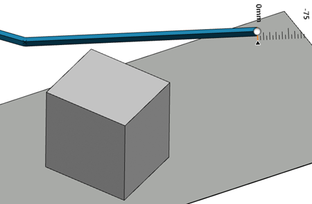
- Optional: Define an offset using the distance editor.
-
To validate your manipulations, click in the 3D area or press
Enter.
The new passing point is added to the branch route. You are now able to continue your branch design by selecting other geometric elements as constraints.
