- From the Formboard section of the action bar, click Synchronize
 .
. - Click Execute.
The Synchronization Report is displayed. The modification of viewing direction is indicated in the Orientation Angle column: the value is changed.
- Click Close.
-
Click Update All
 .
.
-
Open the drawing data window.
- In the Drafting app, from the
View Layout
section of the
action bar, click Front View
 .
. -
Switch to the flatten data window to
create a new drawing of the flatten data.
-
Select a face to choose the orientation of the drawing.
The Electrical Manufacturing Preparation app switches to the
Drafting app. See Drafting User's Guide: Creating Views:
Creating a Front View.
-
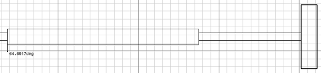
In the drawing, click the background to generate the Front View.
The drawing of the flatten data is created showing the orientation information for the
protective covering in the shape of an arrow with the angle of orientation displayed at its extremity.
The flatten and drawing views display the labels of the protective covering orientation. When you install the harness,
the protective covering sticker is placed properly as per the design harness.