Creating Overall Dimension | |||
| |||
-
From the Dimension section of the action bar,
click Overall Dimension
 .
The Electrical Dimensions dialog box appears.
.
The Electrical Dimensions dialog box appears. -
Hover the pointer over the different segments to see the measure points.
The visible measure points for supports and protections are the entry and exit points. Ctrl + hover over the support or protection to show the middle measure point. To make this a default option, select the Measure Point is always the middle of support and protection check box under Electrical Dimension, available in Me
 > Preferences > App Preferences > 3D Modeling
expander.
> Preferences > App Preferences > 3D Modeling
expander.Important: If the chosen segment is not selectable, a tooltip displays an error message. -
Click the required measure points.
On 3D Extracted Content On Laid-Out Content 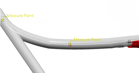
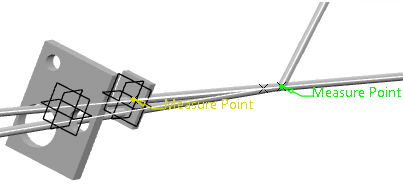
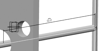
You just need to select key points that intersect with two branches or electrical geometries.
You can first select an electrical component, defining the reference measure point, and a reference marker is created (R5 for example). Then select a second measure point, defining the pointing reference, and a new dimension marker refers to R5 (106.861mm/R5 for example).
-
In the Electrical Dimensions dialog box, click
OK to validate.
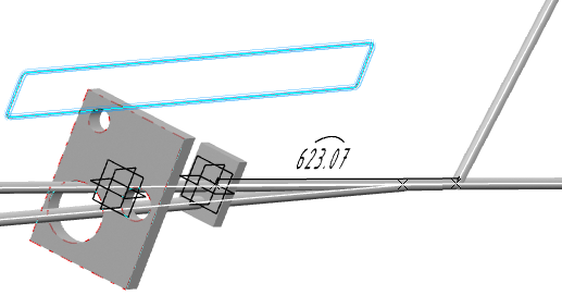
On 3D extracted content On flattened content 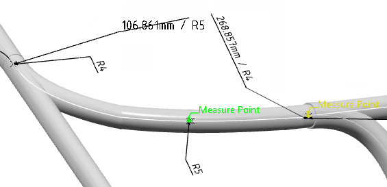
Note: You can reuse a reference measure point (reselect R5) to create several electrical dimensions. In the example below, the reference 3D marker is R5 and it is used by two dimension markers (106.861mm/R5 and 161.996mm/R5).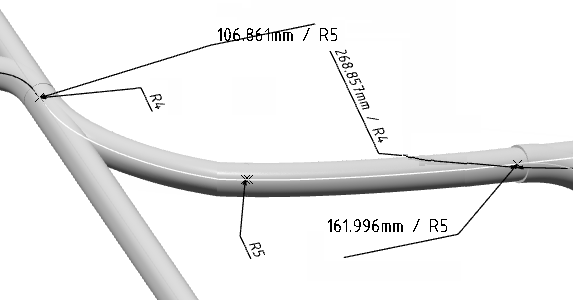
When a 3D marker already exists, select it again or select the electrical components or measure points. It is not possible to select dimension markers because they already contain dimension information. Only FTA annotations are allowed as new selection types.
You can specify the offset distance between the dimension line and the dimensioning element in the Offset distance box, available under Dimension offset in Me
> Preferences > App Preferences > 3D Modeling
section. For more information, see General. Dimension with Default Offset Distance (20mm) Dimension with 10mm Offset Distance 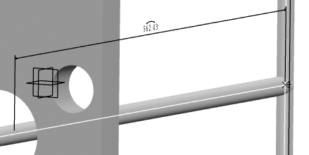
Warning:
|