-
Create a disconnect containing three pins.
Note:
When creating a disconnect, two connector ports are created. Each port has a Style attribute in its properties identifying it as plug or receptacle. For more information about disconnects, see Disconnect Symbol.
-
Double-click the diagram view.
-
In the tree, under Disconnect > Ports,
right-click the plug port and select Place in View.
The symbol associated with the plug part appears and follows your pointer. -
Click the diagram view to
place the plug symbol.
-
On the context toolbar,
click Display Connector and Pins
 . .
-
In the Manage Connector and Pins Display dialog box, select the
pins to displayed. For more information, see Displaying Pins on a Connector.
Notes:
- If the Lock pin multi representation option is selected in
, the pins already represented in a diagram view loaded in session
cannot be selected. For more information, see Native Apps Preferences
Guide: Schematic.
- A component whose pins are already placed in view cannot be placed in view if the
Lock pins multi representation option is selected.
- Click the plug symbol and click Smart Positioning Harness Connector
 on the context toolbar. on the context toolbar. The plug and receptacle symbols are connected. The pins of the receptacle are aligned with the pins of the plug, in the same order. 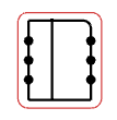 -
Optional: To modify the distance between the end of the harness connector symbol and the last pin, click Offset and modify the values in the Top Offset and Bottom Offset box.
- Click anywhere to validate the connection.
|
 > Preferences > App Preferences > 3D Modeling
, the pins already represented in a diagram view loaded in session
cannot be selected. For more information, see Native Apps Preferences
Guide: Schematic.
> Preferences > App Preferences > 3D Modeling
, the pins already represented in a diagram view loaded in session
cannot be selected. For more information, see Native Apps Preferences
Guide: Schematic.