-
Create a harness connector.
Note:
If the harness connector already exists, right-click it and select Place in View.
Once you have validated the creation of your harness connector, its representation
appears and follows your pointer.
-
Click anywhere, and click Smart Positioning Harness Connector
 on the context toolbar. on the context toolbar.
-
Select the equipment or a pin of the equipment connector.
Notes:
- If only the equipment is placed in the diagram view, with no representation of the
pins of the connector port, you have to choose the port orientation and select the
pin to be displayed in the Ports dialog box.
- If all pins of the harness connector are to be displayed, the
harness connector is displayed with its full representation. For more information,
see About Electrical Component Representation.
- You can set a business rule to define the compatibility between two connectors
(example: two connectors are incompatible if they do not have the same number of
pins). For more information about this business rule, see Functional/Logical Connection Creation Check Business Logic (FLConnectionCreationCheck).
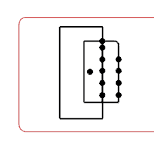
The harness connector is placed and connected with the equipment connector. The
pins are placed and aligned with the pin of the equipment connector, in the same
order.  -
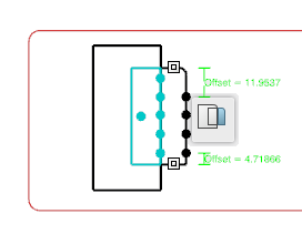
Optional: To modify the distance between the end of the harness connector symbol and the last pin, click Offset = and modify the values in the Top Offset and Bottom Offset box.
-
Click anywhere to validate the position of the harness connector.

|