-
Create an equipment connector. For more information,
see Create an equipment connector.
Once you have validated the creation of your equipment connector, its
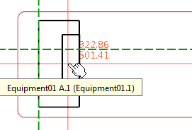
representation appears and follows your pointer. 
-
Place the connector port representation on the equipment and
click.
Notes:
- You can also right-click the connector port in the tree and
select
Place in View.
- Placing a connector port representation without the equipment
representation in the diagram view is also possible.
-
On the context toolbar, select Display Connector Port
and Pins
 . .
The Manage Connector and Pins Display dialog box
appears.
-
In the
Step box,
type the step value to
define the distance between two pins.
Note:
The default step is defined in
.
For more information, see
Native Apps Preferences
Guide:
Schematic.
-
In the
Offset box, type the offset value to define
distance between the top of the connector port and the first pin.
-
Select the boxes of the pins to be displayed.
Notes:
- If the
Lock pins multiple representations
option is selected in
, the pins
already represented in a diagram view loaded in session cannot be selected.
For more information, see
Native Apps Preferences
Guide:
Schematic.
- A component whose pins are already placed in view cannot be
placed in view if the
Lock pins multiple representations
option is selected.
-
Click
OK.
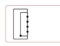
The pins appear on the connector port.

-
Click anywhere to validate the connector port position in the
diagram view.
The connector port is placed in the diagram view and is graphically linked with the
equipment representation. If you modify the orientation of the equipment
representation, the orientation of the connector port representation is also
modified. Notes:
- If the connector port is not placed on the equipment, the graphical
link between the two representations is not created.
- If all pins of the connector port are displayed,
the connector port is displayed with its full representation. For
more information, see About Electrical Component Representation.
|