-
Activate the diagram view.
-
From the
Edition section of the action bar, click
Create Equipment Connector
 .
.
-
In the tree, select the equipment.
-
In the
Create Equipment Connector dialog box.
-
Enter the name of the connector.
-
Choose the type of the connector.
-
Choose the type of pins.
-
Enter the number of pins to be inserted.
-
Optional: Type a prefix for the pins'
names.
-
Type the name of the first pin.
Note:
If there is more than one pin, their names
follow the alphabetical/numerical order according to the name of the first pin.
-
Optional: Type a suffix for the pins'
names.
-
Click
Add.
The pins appear in the
Pins To Be Created area.
Note:
To remove pins, select them in the
Pins To Be Created area and click
Remove.
-
Click OK to create the equipment connector.
-
Click the diagram view at the convenient place to insert the
symbol.
The symbol is placed and a
context toolbar appears.
-
Optional: To modify the position of the
symbol, select one of the following commands:
- Flip horizontally
- Flip vertically
- Rotate to left by 90 degrees
- Rotate to right by 90 degrees
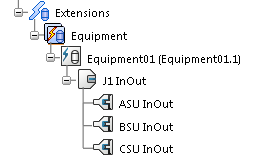
The
Extensions node displays this new hierarchy.