-
From the Edition section of the action bar,
click Create New Reference
 . .
The New content dialog box appears.
- In the New content dialog box, expand the Electrical Logical tab and
right-click Logical Net.
-
Select the Set attributes at creation option.
Note:
This option remains selected when creating another net.
-
Click Logical Net.
The Logical Net dialog box appears.
-
Type a name for your net reference and click OK.
-
Click the first component.
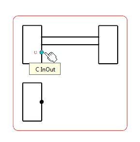
A context toolbar appears, containing commands to create an elbow or a straight route line.
-
Click at a convenient place to insert the first connector.
A context toolbar appears, containing the command to create the on-sheet connector.
-
Click Sheet Connector.
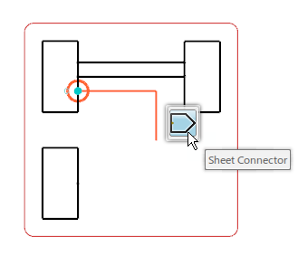
The first on-sheet connector is created.
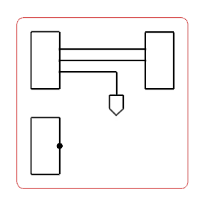 - In the tree, right-click the net reference and select Add Net Connection
 . .The Route Command dialog box appears. - Select the second component.
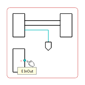
A context toolbar appears, containing commands to create an elbow or a straight route line.
- Click at a convenient place to insert the second on-sheet connector.
A context toolbar appears, containing the command to create the on-sheet connectors. - Select Sheet Connector.
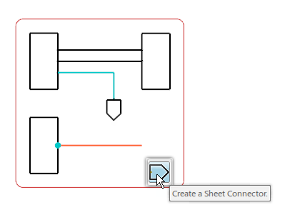
The on-sheet connector is created for the second component. 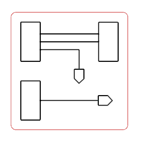 Note:
To delete the sheet connector, right-click the sheet connector symbol and select Delete. The sheet symbol and the route connected to it are removed from the diagram view.
|