About Edge Fillets as Local Modifiers | |||||
|
| ||||
More about Propagation Modes
Two propagation modes are available:
-
Minimal: Edges tangent to selected edges can be taken into account to some extent. The app continues filleting beyond the selected edge whenever it cannot do otherwise. In the example below, the fillet is computed on the selected edge and on a portion of tangent edges:
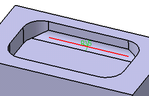
-
Tangency: Tangencies are taken into account to fillet the entire edge and possible tangent edges.

Conic Parameter
Conic parameter under Options allows you to vary the section of the fillet. For a parameter comprised between or equal to:
- 0.5, the resulting curve is a parabola.
- 0 < parameter < 0.5, the resulting curve is an arc of an ellipse.
- 0.5 < parameter < 1, the resulting curve is a hyperbola.
- Conical fillets do not handle twist configurations. If a twist is detected, the fillet operation fails.
- Conical fillets may produce internal sharp edges due to a curvature discontinuity of the fillet supports. Healing is used to smooth these sharp edges.
- If the fillet surface curvature is lower than the support curvature, fillet surface trimming may fail. In such cases, the conic parameter has to be decreased.
Additional Options
There are few more additional options available under Options:
Edges to keep:
When filleting an edge, the fillet may sometimes affect other edges of the part, depending on the radius value you specified. In this case, the app detects these edges and stops the fillet to these edges.
Edge to be filleted:
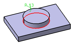
The upper edge is not filleted:
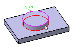
A message appears asking if you want to select the edge that you do not want to fillet.
- If you want to select the edge:
- Click Yes.
The Update Diagnosis dialog box appears.
- Click Edit.
- In the Edge Fillet.x dialog box, click in the Edges to
keep box and select the required edge in the
geometry.
The selected edge is highlighted indicating that it will not be affected by the filleting operation.
- Click Yes.
- If you do not want to select the edge, click No.
- If you want to select the edge:
Limiting Elements:
Limiting element lets you intersect the fillet with one or more planes. What you need to do is either:
- Select that plane or
- Click one point located on the edge to be filleted. After clicking, a blue disk appears indicating the limiting element. The intersection with the fillet will then stopped at that point.
An arrow appears on the plane to indicate the portion of material that will be kept. Clicking this arrow reverses the direction and therefore indicates that the portion of material that will be kept will be the opposite one.
Blend Corners:
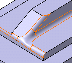
Sometimes, while filleting you can see that corners resulting from the operation are not satisfactory, such as:

Blend Corners quickly reshapes these corners . Clicking Blend corners detects the corner to reshape and displays it both in the box and in the 3D.

For each edge, enter a value in the setback distance box. The setback distance determines for each edge a free area measured from the vertex along the edge. In this area, the system adds material to improve the corner shape. The result looks like this:
What you Cannot Select
- Fillet is a feature modifier and
in that sense, you are not allowed to select edges belonging to
different shapes (different bodies). In the example below, you
cannot select the third edge pointed to by the arrow because it
belongs to a distinct shellable feature.
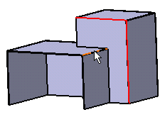
Alternatively, you can either create a second functional fillet or apply Part Design Edge Fillet .
.
- You cannot fillet the internal edges or faces of a shellable feature.
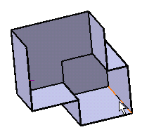
Alternatively, you can use Part Design Edge Fillet .
. - You cannot select edges intersecting two distinct feature
modifiers.
Alternatively, you can use Part Design Edge Fillet
 .
.
- You can select external pocket's edges, but ensure that the
radius value you enter does not affect the pocket shape.
Alternatively, you can reduce the fillet angle
value or use Part Design Edge Fillet
 .
. - You can select the edges of push or pull features, but ensure
that the radius value you enter does not affect the push or pull
shape.

Alternatively, you can reduce the fillet angle value or use Part Design Edge Fillet .
.