-
From the
Create section of the
action bar,
click
Shellable Feature
 . .
A
feature can have one of the following shape definitions:
Prism
 ,
Sweep ,
Sweep
 ,
Revolve ,
Revolve
 ,
Thick Surface ,
Thick Surface
 , or
External Shape , or
External Shape
 . For more Information, see
Working with Shape Definitions. . For more Information, see
Working with Shape Definitions.
Prism
 is selected as the default shape definition.
Note:
You can change the shape
definition.
The dialog box for the feature changes according to the
options offered by the shape.
-
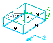
Select the profile to be extruded.
-
Create a basic prism as explained in the
Prism
task.
- Optional:
In the Draft tab,
-
From the Draft behavior list, select
Intrinsic to feature.
-
Set profile plane as the neutral element and enter the required value
to define the draft angle.
- Optional:
In the Fillet tab,
-
Select among the following check boxes and enter the required values,
to fillet the corresponding edges:
- Lateral radius to fillet lateral edges
- First radius to fillet top edges
- Second radius to fillet bottom edges
-
Select the Fillet profile ends check box, to
fillet the end faces of open sketches.
-
Select the Draft fillets check box, to fillet
the drafted edges.
-
From the Type list under Intersection
Fillet, select among the following, to create fillets at
required intersections:
- Intersection with Core/Cavity
- Intersection with Core
- Intersection with Cavity
-
Select the Fillet radius check box to create
fillet by adding material to the feature.
-
Select the Round radius check box to create
fillet by removing material from the feature.
-
Select the Preserve shell thickness check box to
maintain the thickness at fillets.
-
Click
OK.
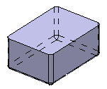
Shellable Prism.x is added to the
tree
in the
Solid Functional Set.x node.
By customizing the view (using
Hidden edges points), you can notice that
the prism is hollow .
By default, the shellable feature has no opening.

-
To edit the shellable feature, double-click the
Shellable Prism.x node in the
tree
or click
Shell Properties
 in the
Object Properties
 panel. panel.
-
In the Shell Properties.x, select the required faces in
Faces to remove box.
-
Enter the required wall thickness in the Thickness
box.
-
Click
OK.
The selected faces are removed. The shell is edited.

|
 .
.
 ,
Sweep
 ,
Revolve
 ,
Thick Surface
 , or
External Shape
 . For more Information, see
Working with Shape Definitions.
Prism
 is selected as the default shape definition.
Note: You can change the shape definition. The dialog box for the feature changes according to the options offered by the shape.
 to sketch the profile.

 in the
Object Properties
 panel.

