Creating a Stamp Function | |||||
|
| ||||
-
From the Design section of the action bar,
click Stamp Function
 .
The Stamp Function Definition dialog box is displayed.
.
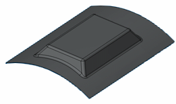
The Stamp Function Definition dialog box is displayed.Tip: This dialog box is interactive: it is dynamically updated each time you modify an option to represent how the chosen options will influence the result. The blue star near the option name means that it is a mandatory input. - Select the stamp type:
- Support Based Stamp: the support surface is mandatory. This kind of stamp is not contextual.
- Offset Based Stamp: the support surface is computed using an offset of the current context, its shape is recomputed every time the context is modified. This kind of stamp is contextual.
Important: The stamp must lie within the support surface. - Support Based Stamp: the support surface is mandatory. This kind of stamp is not contextual.
- Optional: Define the Draft Direction, i.e. the direction for the side faces, which are drafted from the kept part of the support surface.If it is not valuated, the draft is computed normally to the support surface.Note: You can create a draft direction using the Draft Property command
 . For more information, refer to Creating Draft Properties.
 - Optional: Define the other parameters:
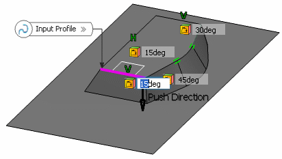
- Draft Angle: defines the angle between the draft direction or the support surface and the lateral faces.
You can choose between a constant and a variable draft angle by right-clicking the angle value.
For a variable draft, a profile is mandatory. Draft angles are automatically associated to each tangent piece of the profile. When you click a value to modify it, it is highlighted in the work area:
Note: Contextual options are available when right-clicking a location point:- You can define a variable law by selecting Define this piece as variable.
- You can remove a location value by selecting Remove.
- You can add location points by selecting Add new draft location points on the highlighted piece.
- You can define a null slope at the law extremities by selecting Set zero slope at law start / end.
Note: Contextual options are available when right-clicking and end:- You can create a variable stamp controlled by points by selecting Select draft locations points on the highlighted piece.
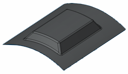
- Lateral Fillet: defines the radius of the fillet that is computed on the lateral edges. If no radius is defined, no fillet is computed.

- Support Fillet: It defines the radius of the fillet that is made on the top edges. If no radius is defined, no fillet is computed.
- Intersection fillet radius: defines the radius of the fillet that is made on the edges between the stamp and the context. If no radius is defined, no fillet is computed.
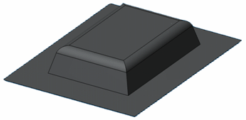
- End angle: defines the angle between the normal to the context and the end faces.
- End radius: defines the radius of the end face that links the top faces and the end faces.Note: You can create a radius using the Radius Property command
 . For more information, refer Creating Radius Properties.
 - Internal intersection fillet: when the input profile is multi-domain, there are edges between the different beads resulting from each domain.

- Setback mode and distance: this option is only available with an offset based stamp. An offset of the context has to be performed to get the support surface. The profile is projected on the context and a parallel curve is computed on this context to offset only the required area.Note: In automatic setback mode, the offset distance corresponds to the height of the stamp.
- Length: this option is only available with a support based stamp. The length corresponds to the length of the side walls. This length should be manually defined as it is not automatically computed.
- Orientation: the orientation of the swept lateral surfaces only relies on the support surface and the sign of the function. Nevertheless, you can invert the orientation.
- Draft Angle: defines the angle between the draft direction or the support surface and the lateral faces.
You can choose between a constant and a variable draft angle by right-clicking the angle value.
- Click OK to create the stamp.The element (identified as Stamp Function) is added to the tree.
 Note: For more information, refer Displaying and Modifying the Dimensions of a Feature Directly.
Tip: You can use the  icon to create design tables. See Knowledge
Basics: Managing Relations : Design Tables.
icon to create design tables. See Knowledge
Basics: Managing Relations : Design Tables.