-
Select the Front View.x annotation plane.
-
From the
Annotation
section of the
action bar, click Geometrical Tolerance
 .
.
-
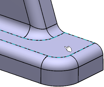
Select the required face.
The Geometrical Tolerance
dialog box appears. This dialog box allows you to:
- Specify as many specification lines as you want (with the Up and
Down arrows).
- Insert several modifiers anywhere in a tolerance or a reference.
- Add notes upper and lower the set of specification.
Notes:
- At this step, you can apply the parameter values of an existing
geometric tolerance to the tolerance you are creating: to do this, select the
existing geometric tolerance.
- If you have selected the Use style values to create new objects check
box in
expander, the Geometrical Tolerance
dialog box is automatically completed with custom style values (as defined
in the Standards Editor). In this case, properties in the Object
Properties panel and the Tools
Palette are not available during the creation of the
geometrical tolerance.
If you have not selected this option, the
Geometrical Tolerance dialog box is
automatically completed with the last entered values (if any). In this
case, properties in the Object
Properties panel and the Tools
Palette are active during the creation of the
geometrical tolerance.
- You can reset the current style values in the
Geometrical Tolerance dialog box at any time by
clicking
Reset.
-
In the Geometrical Tolerance dialog box, perform the
following operations:
-
Under Add Tolerance, click the required
tolerance indicator to add it to the current
feature.
You can add as many tolerances as required.
The tolerance indicator is added below the
previous one in a separate line. Each line is represented by tabs in the
Edit Tolerance section.
-
Under Edit Tolerance, select the tolerance
indicator.
You can select the Remove Line check box to
remove the selected line. This option is unavailable if the selected
tolerance line is the only one.
-
In the Edit Tolerance box, enter the tolerance
value.
-
In the Reference boxes, add references.
You can add multiple references.
-
Select an engineering symbol.
-
In the Auxiliary Feature Indicators list, select
a local indicator.
You can select the following local
indicators:
- Intersection Plane: Identifies a line on
an extracted surface or a point on an extracted line. It is
placed to the right of the tolerance indicator as its extension.
- Orientation Plane: Identifies the
orientation of the tolerance zone. It is placed to the right of
the tolerance indicator as its extension.
- Collection Plane: Identifies a closed
compound contiguous feature. It is placed to the right of the
tolerance indicator after the tolerance frame. It can be
parallel to the projection plane in which the specification is
indicated.
- Direction Feature: Identifies the
direction of the width of the tolerance zone. The direction
feature is a cone, a cylinder, or a plane constructed from the
datum or datum system indicated in the second compartment of the
direction feature indicator. The geometry of the direction
feature depends on the geometry of the tolerance feature. It is
placed to the right of the tolerance indicator as its extension.
Note:
You can add maximum three non-identical local
identifiers for a single tolerance.
-
In the Auxiliary Feature Text Indicator box, add
an indication text.
You can also select engineering symbols.
-
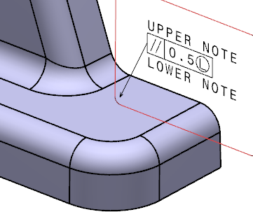
In the Global Text Indicators boxes, add an
upper and a lower text.
You can also select engineering symbols.
You can add new
3D leaders in the
3D area
or switch current 2D leaders to 3D to position the leader outside the
annotation plane.
For more information, see
Adding a 3D Leader.
-
Click OK to accept the values or
Reset to clear all values.
The geometrical tolerancing annotation is attached to the part.
The geometrical tolerance entity (identified as Geometrical
Tolerance.xxx) is added to the tree under the Geometrical Tolerances node.
|
 > Preferences > App Preferences > 3D Modeling > Mechanical Systems
expander, the Geometrical Tolerance
dialog box is automatically completed with custom style values (as defined
in the Standards Editor). In this case, properties in the Object
Properties panel and the Tools
Palette are not available during the creation of the
geometrical tolerance.
> Preferences > App Preferences > 3D Modeling > Mechanical Systems
expander, the Geometrical Tolerance
dialog box is automatically completed with custom style values (as defined
in the Standards Editor). In this case, properties in the Object
Properties panel and the Tools
Palette are not available during the creation of the
geometrical tolerance.