You can add a leader only to one annotation at a time, so, you need to select only one
annotation before selecting the Add Leadercontext menu command. Any multiple selections are cleared.
Creating Numerous Leaders
To create as many leaders as required for an existing text, select Me > Preferences > Customize and create the Add Leader command in a separate action bar. You can then double-click the Add Leader command and
click to locate the leaders to be created.
Snapping the Leader on Privileged Directions
When adding a leader to an annotation, or an extremity to a leader, you can snap the
orientation of the corresponding segment on the following privileged directions:
Horizontal and vertical directions:
Computed in the sheet for annotations oriented in the sheet.
Computed in the view for annotations oriented in the view.
Reference normal and tangent directions: The reference can be a geometry or
an annotation.
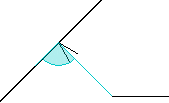
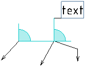
The leader attachment point or the leader breakpoint, from which the new extremity is
created, is considered as a fix point. However, you can move the leader so that the
new leader is snapped on the privileged direction. When the leader extremity is
snapped on any of the privileged directions, it turns to cyan color.
You can activate or deactivate the Snap on Privileged
Direction option from the Annotation section of
the action bar.
Note:
In 3D Tolerancing & Annotation and Generative Functional Tolerancing, when manipulating the extremity leader, if the leader has a positional link
on a reference, only the snap on perpendicular to the reference and reference
tangent directions are available. When there is no reference selection, snap on
horizontal and vertical directions is available.
The following commands provide the snapping on privileged directions:
Text with Leader
Datum Target
Geometrical Tolerance
Coordinate Dimension
Welding Symbol
Flag Note
NOA
The following points are considered when snapping a leader extremity on its
privileged directions:
The orientation is associative only if the leader is snapped on the
perpendicular direction with respect to the reference.
The selection of a geometry or an annotation: If an annotation providing
attachment points is selected as a reference, the annotation position is
snapped on the selected attachment point and its leader is removed.
The snapping on the paper grid: If Snap by default (SHIFT toggles)
check box is selected in Me > Preferences > App Preferences > 3D Modeling > Mechanical Systems > Drafting > Handles expander, under Paper Grid, and no reference is
selected, the position is first snapped on the privileged direction and then on the
closest grid point or grid line (if no grid point is located on the privileged direction).
Important:
If Text check box is selected in Me > Preferences > App Preferences > 3D Modeling > Mechanical Systems > Drafting > Annotation and Dress-Up expander, under Create leader extremity normal to
reference (Ctrl toggles), the text leader is oriented
perpendicularly to the reference, by default. In this case, the snapping on
privileged directions is no more available when selecting a reference. Though in
this case, the orientation link is created, because Snap on
privileged directions check box is selected.
Snapping Using Shift
If you press Shift when a leader is snapped on a privileged
direction, the leader stays snapped on this privileged
direction, whatever the position of the mouse pointer is till
you release Shift.
If you press Shift when the leader is snapped on more than one
direction, the leader cannot be moved anymore.
In this case, Shift no more toggles the snapping
on the paper grid.
If the Snap by default (SHIFT toggles) check box is selected, the
position is snapped on the privileged direction and then on the
closest grid point or grid.
If the Snap by default (SHIFT toggles)
check box is cleared, the position is snapped only on the
privileged direction.
Positioning the Leaders
You can keep the leaders at the standard positions with respect to the specific text frame
using the Allow only standard positionscontext menu command. Note that if you do not select this option, you can position the leaders
with respect to the anchor point (for example, top left, top right, middle left,
etc.).
When you position an annotation that on an existing annotation using an attachment point, an
associative positional and orientation link is created, and the leader is
automatically removed.
While creating an annotation, using the Leader extremity normal to
reference option from the tools palette, you can create a leader
perpendicular to the reference geometry. The tools palette option
is available for both semantic and non-semantic annotations. Press
Ctrl to toggle between the free leader and perpendicular
leader.
The orientation of the various segments of a leader can be snapped while moving:
An extremity of a leader:
If the extremity position is constrained by a positional link but
can still move, the corresponding segment orientation is snapped.
If the extremity is constrained by an orientation link, it cannot be
moved.
If the extremity is not constrained, the corresponding segment
orientation is snapped on horizontal and vertical directions.
A breakpoint of a leader:
All
segments attached to the breakpoint are snapped based on their order of
creation.
The following segments are ignored:
Terminal segments whose extremity is constrained by an orientation link.
Terminal segments that are defined as rigid.
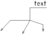
Note:
When you press Ctrl, the breakpoint is
placed so that both the segments to the breakpoint and the first
segment from that breakpoint are vertical and horizontal or vice
versa.
Before
Ctrl pressed
After
An annotation has one or several leaders:
The leader segments that are directly attached
to an annotation that have their orientation snapped when moving this
annotation. The leaders are snapped according to their order of
creation. That is, first created segment is snapped first.
The following leaders are ignored:
The leaders with no breakpoint and whose extremity is
constrained by an orientation link.
The leaders with no breakpoint and which are defined as rigid.
Note:
If several annotations are selected, the snapping is done only on
the annotation is currently under manipulation. The other
annotations are moved independently of their leaders.
You can position the leader by specifying its extremity out of the
current annotation plane. To do so, switch the 2D leader to 3D leader
and then manipulate the extremity to the required position.
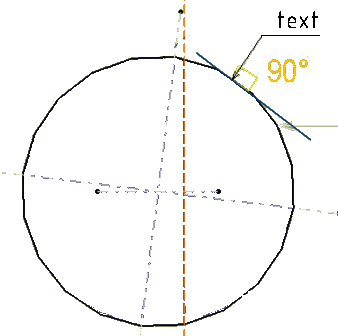
When the annotation plane is not parallel to the referenced curved geometry, the curve
tangency on the leader extremity is used to determine the perpendicular orientation
of the leader.
Adding an Extremity Link
It is possible to add an extremity link to a leader.
If the leader extremity does not have a
link, the Add Extremitycontext menu command is available. To add an extremity, right-click the yellow control point
and select Add Extremity. It creates a positional link to the
selected reference. If you press Ctrl, an orientation link is
created.
When the extremity is added, you can remove, replace, or make the extremity perpendicular
using the following context menu commands:
Remove: Removes the extremity link.
Perpendicular: Makes the extremity link perpendicular
with respect to the reference.
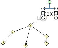
Adding a 3D Leader
You can add 3D leader for the annotations with existing leaders in the 3D area
or switch the current 2D leaders to 3D to position them outside the annotation
plane. To do so, you can do either of the following:
Right-click the annotation, select Add Leader and
then in the Tools Palette select the
3D or 2D/3D. For more
information, see Adding Leaders and Using Breakpoints.
Right-click the arrow end of the leader and select Switch to 3D
Leader. When you switch to the 3D leader, the diamond symbol
at the extremity of the leader displayed parallel to screen.
You can add 3D leaders for following annotations:
Annotations:
Text with Leader
Flag Note with Leader
Datum Feature
Datum Target
Datum Target
Note Object Attribute
Note Object Attribute instantiation
Geometrical Tolerance
Welding Symbol
Roughness
Coordinate Dimensions
Annotation created using Tolerancing Advisor:
Text with Leader
Flag Note with Leader
Datum Feature
Datum Target
All Geometrical Tolerances
Roughness
You can select preferences to specify the positions of the annotation body and the arrow end
of the leader. For more information, see Dimension Default Position Along View Normal.
 > Preferences > Customize and create the Add Leader command in a separate action bar. You can then double-click the Add Leader command and
click to locate the leaders to be created.
> Preferences > Customize and create the Add Leader command in a separate action bar. You can then double-click the Add Leader command and
click to locate the leaders to be created. 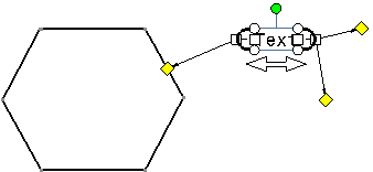
 > Preferences > App Preferences > 3D Modeling > Mechanical Systems
expander, under Paper Grid, and no reference is
selected, the position is first snapped on the privileged direction and then on the
closest grid point or grid line (if no grid point is located on the privileged direction).
> Preferences > App Preferences > 3D Modeling > Mechanical Systems
expander, under Paper Grid, and no reference is
selected, the position is first snapped on the privileged direction and then on the
closest grid point or grid line (if no grid point is located on the privileged direction). 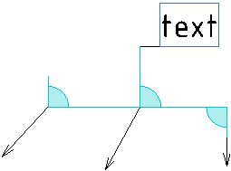
 :
: