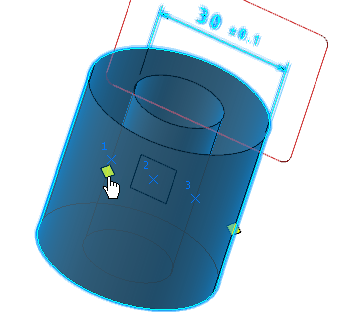
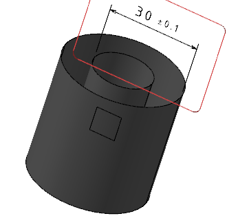
Creating Semantic Dimensions | ||||||
|
| |||||
-
From the Annotation section of the action bar, click Tolerancing Advisor
 .
.
-
In the Semantic Tolerancing Advisor dialog box, select
the two cylindrical surfaces.
The dialog box is updated accordingly.Notes:
- If the cylindrical surfaces have opposite material senses, various new options are proposed along with linear dimensions.
- If cylindrical surfaces have same material senses, only linear dimensions are proposed.
-
In the dialog box, click Distance Creation.
The Limit of Size Definition dialog box appears with the following options:
- General Tolerance: Lets you define a pre-defined
class of tolerance. See Tolerances
for the default class
setting.
You can also define the customized general tolerance from the General Tolerance list. The customized tolerances appear on the basis of following selections:
- Standard defined (ISO, ANSI-ASME, or JIS) under Annotation Set Creation. For more information, see Annotation Set Creation.
- General tolerances defined in the resource table using Data Setup.
Important: - When you add the customized tolerances in the
resource excel sheet to be defined in the resource
table, follow the below guidelines:
- In the first column, define the standard and
dimension type, e.g. ISO.LinearSize.
This decides for which conventional standard (ISO, ANSI-ASME, or JIS) the customized standard is going to appear.
- In the second column, define the general tolerance standard and class, e.g. ISO 2768 - f.
- In the third and the fourth column, and every
third column after, define the nominal values
range in increasing order.
The variation lower limit and upper limit for the nominal value range need to be defined in the column next to the larger nominal value column.
- To specify the values in different units
(other than millimeter or degree), a column named
Unit must be defined as the
last column of the sheet.
- To specify the values in different units
(other than millimeter or degree), a column named
Unit must be defined as the
last column of the sheet.
Every row will have its own unit as specified in the Unit column. All the values mentioned in that row will be in specified unit only. You can specify below units:
- Length: Micrometer, Millimeter, Meter, Centimeter, Kilometer, Foot, or Inch.
- Angle: Degree,Minute,Second or Degree, Radian, Grade.
All these values will be converted as per current dimension unit, precision, and display factor and will then be displayed in Limit of size dialog box and the tooltip.
If the values of angles are expressed only in seconds or in minutes or the combination of both, specify the Degree,Minute,Second unit in the Unit column.
- For angle values and nominal range values, specifying respective symbols (for example, specify " after value of second) are mandatory after their corresponding values.
- When the unit column is not defined, the default units for length and angle are millimeter and degree respectively.
- The serial column number needs to be specified till the last column of the sheet (with at least one filled cell value).
- To specify the values in different units
(other than millimeter or degree), a column named
Unit must be defined as the
last column of the sheet.
- In the first column, define the standard and
dimension type, e.g. ISO.LinearSize.
- The customized general tolerances does not
appear under General tolerance
class available in
Me
 > Preferences > App Preferences > 3D Modeling > Mechanical Systems
> 3D Tolerancing
& Annotation > Tolerancesexpander.
 - When you open a 3D model with dimension having general tolerance values which are not defined in the resource sheet, only the standard name is displayed in the tooltip. When you edit the dimensions, they are not proposed in the list.
- When you add the customized tolerances in the
resource excel sheet to be defined in the resource
table, follow the below guidelines:
For more information, see Data Setup User's Guide: Resource Tables and Data Setup User's Guide: List of Resource Set IDs: 3D Modeling: Drafting and 3D Master Resources: Available Resources.
- Numerical Values: Lets you define the Upper Limit and optionally the Lower Limit (provided you uncheck the Symmetric Lower Limit option).
- Tabulated Values: Lets you define fitting
tolerances. By default, the tabulated value is H7.
When you create dimensions, the uppercase letter (for a hole or a slot) or the lowercase letter (for a shaft or a tab) of tabulated values appear based on the selected feature. You can also enter the letters manually.
For more information, see Standards: Normative References: ISO 286, ANSI B4.2.
- Single Limit: Lets you enter a minimum or maximum tolerance value. Use the Delta / nominal box to enter a value in relation to the nominal diameter value. For example, if the nominal diameter value is 10 and if you enter 1, then the tolerance value will be 11.
- Information: Lets you to set the dimension as information (ISO-based standards) or reference (ASME-based standards). The information or reference dimension is displayed enclosed by parentheses in geometry window.
- Option: Lets you to specify the following
geometrical tolerance symbols:
- Envelop Condition: Lets you specify the envelope condition as a modifier.
- Statistical Tolerancing: Lets you specify the statistical tolerancing as a modifier.
- Free State: Lets you specify the free
state symbol
 on semantic dimensions to ensure dimensional tolerances in
free state during its creation or edition.
Notes:- If the Propose the last created tolerance
values check box is selected under New
Size Tolerances Creation in
Me
 > Preferences > App Preferences > 3D Modeling > Mechanical Systems
> 3D Tolerancing &
Annotation > Tolerances expander, the last tolerance type and values defined
in the previous command are proposed as default for the next
command.
 -
For tabulated values:
- If you manually enter the lowercase letter for hole and uppercase letter for shaft, the same is proposed as default for the next hole or shaft selection.
- If you select a vertex or an edge of a feature, default tabulated value is applied.
- If the material sense for the selected geometries is not identified and selected geometries do not define the exact hole or shaft system, by default, the uppercase letters is applied.
- General Tolerance: Lets you define a pre-defined
class of tolerance. See Tolerances
for the default class
setting.
-
Move the handles to display the distance between required points.

- Click OK anywhere in the 3D area.
-
Click Close in the Semantic Tolerancing
Advisor dialog box.
The semantic dimension is created between the edges of the cylindrical surfaces.
