Creating a Breakout View | ||||||
|
| |||||
-
From the View Layout section of the action bar, click Breakout View
 .
.
-
Click as many points as required to create the profile, and click the first
point to close the profile or double-click to end the profile creation.
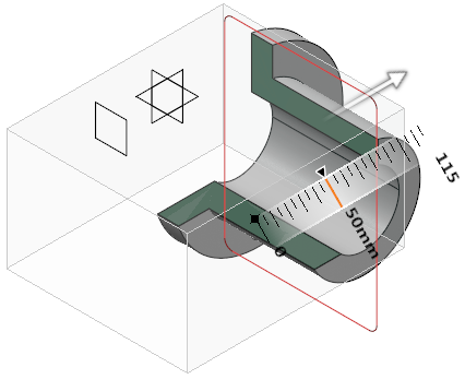
The Breakout dialog box appears, displaying the 3D part corresponding to the generated view and an arrow indicating in which direction the breakout is created.
Note: The 3D viewer lets you manipulate the 3D part. It also lets you visualize a view plane or a 3D point and use them to define the depth of the breakout. -
Perform either of the following operations:
- In the 3D viewer, drag the arrow to the required location. The breakout is not associative with any element.
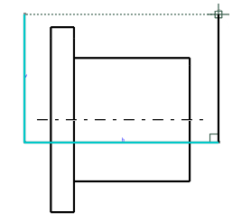
- In the drawing, select an axis, a centerline, or an edge
(circular or linear) of a perpendicular view. The 3D plane is moved
accordingly. This method lets you break the view through a hole or a face,
for example. The breakout is associative with the selected element.
For example, select the centerline to use it as an extremity plane, as shown below:
- In the 3D viewer, perform the following operation:
- Click the arrow to activate the reference element selection.
- Select a face, a circular edge, an axis system, a 3D point, or a 3D
plane as a reference element to define the depth of the breakout.
In this case, the breakout is associative with the selected element.
- Under Parameters, in the
Offset or X box,
enter a value.
You can also define the depth by dragging the arrow.
You can select any of the following for plane translation during reference selection:
- Translate plane to geometry
 : Moves the plane according to the selected element. By
default, this option is selected.
: Moves the plane according to the selected element. By
default, this option is selected.If the selected element is perpendicular to the viewing plane, the breakout plane is positioned at the center of the element. Else, it is positioned at the start or end of the element.
- Translate plane to bounding box
 : Lets you select a plane using the bounding box of the
selected element. The selected face is highlighted with cyan
color.
: Lets you select a plane using the bounding box of the
selected element. The selected face is highlighted with cyan
color. - Translate plane along main axis
 : Lets you translate the plane along the main axis.
- Optional:
Under Display, click the following options to change the
visualization accordingly:
- Clipping tool:
- Display background and clipping tool
 : Shows the 3D object and the clipping tool.
 - Display clipped background and clipping tool
 : Shows the clipped 3D object and the clipping tool.
 - Display clipping tool
 : Shows only the clipping tool.
- Display background and clipping tool
- Transparency: Modifies the transparency of the clipping tool. By default, the value is 200.
- Turn viewpoint: Turns the viewpoint of the 3D object to Iso, Front, Rear, Left, Right, Top, or Bottom.
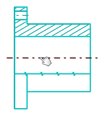
The breakout view is created.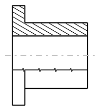
- Clipping tool: