-
Double-click the required view to activate it.
-
click Text with Leader
 . .
-
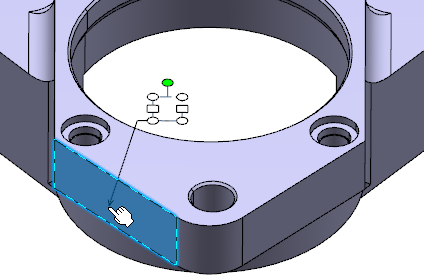
Select a face to position the arrow end of the leader.

-
Position the annotation at the required location.
Note:
Press Ctrl to position the annotation according to
the pointer, if the Allow to indicate annotation body position
(CTRL toggles) check box is cleared in the preferences.
-
In the Text Editor dialog box, enter the required text.
-
Click OK.
The text (identified as Text.xxx) is added to the tree under the Notes sub-node.
-
Optional: Move the leader so that the leader extremity is snapped
on the privileged direction.
The privileged directions are horizontal, vertical, reference normal and
reference tangent directions. Note:
When copying or pasting an engineering
symbol (such as φ Phi for example) in the text editor, the symbol is pasted
as a plain character. As a result, if the symbol does not exist in the
current font, the resulting character in the drawing may be
different.
-
Click in the 3D area.
-
Right-click the text with leader and select Switch to 3D
Leader to make the 2D leader a 3D leader.
The handle at the arrow end of the leader becomes parallel to the screen. Based on
the preferences specified you can modify the position arrow end of the leader.
For more information, see Annotation Default Position Along View Normal
.
|