Blend Surface Dialog Box - Main Area | |||||||||
|
| ||||||||
Blend Type
- Single/Global blend
-
-
 Single
- Creates a blend surface with the options of the Options and Coupling tabs. 2nd Curve is automatically used as moving frame.
-
 Global
- The Moving Frame tab is additionally available for aligning the iso-curves of the blend surface. The Coupling tab is only available if 2nd Curve is selected as moving frame type.
-
- Tangent Length
- Controls the control point distribution by the inner tension handles. For computing the
cross tangent lengths, the following modes are available:
- Auto
- Automatically computes the tangent lengths.
- Constant
- Uses a constant length as source for all other tangent lengths.
- Ratio
- Adapts the second and all following control point segments
(depending on the set continuity) to the first control point
segment.
This is done by assuming, that the length ratio between the first and the second control point segment is the same as the length ration between the second and the third one, and so on.
Side 1/2
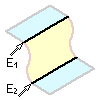
- Edge 1/2
- Selects 1st and 2nd connecting edge.
By default, the edge selected first is used as the spine curve for defining the moving frame. You can, however, select any other curve as spine curve (see Moving Frame tab).
If an offset or isoparametric curve is selected as the input element, you can modify certain parameters of these curves by handles directly in the Blend Surface command (see Curve Offset and Isoparametric Curve as Input Features).
- Support 1/2
- Creates a blend patch into the inside of a surface.
For this, existing curves from Edge 1 and Edge 2 are projected onto the supports in a patch normal direction to generate surface curves. These curves are then used as the connecting edges.
Note: The creation of a surface blend into the inside of a surface requires the manual creation of an iso-curve (see Creating Isoparametric Curves on Surfaces).
If you do not use a support, the result is created with G0 continuity. If you select a support surface, the continuity can be G0, G1, G2, or G3.
Approximation Tab
For the general description of the Approximation tab, see the corresponding related topic. The Approximation tab of the Blend Surface dialog box includes the following additional options:
- Blend Surface Segmentation
-
- Sep. Spine
- The segmentation is taken from the curve selected under Separate Spine on the Moving Frame tab.
- Sep. Spine and Side 1
- The segmentation is taken from the curve selected under Separate Spine on the Moving Frame tab and Side 1.
- Sep. Spine and Side 2
- The segmentation is taken from the curve selected under Separate Spine on the Moving Frame tab and Side 2.
- All
- The segmentation is taken from the curve selected under Separate Spine on the Moving Frame tab and Side 1 and 2.
More Info
Displays deviations and output results.
- Display
- Displays values in the work area.
- U+V
- Displays the UV vectors of curves and surfaces.
- MFT
- Displays the local coordinate system for the moving frame type.
- Apply Modes
- Defines the update mode of the active feature while editing it.
- Dynamic
- Feature update occurs dynamically when moving handles or editing parameter values by sliders in the dialog box.
- Static
- Feature update occurs only after releasing the handle.
- Preview
- Displays a preview when geometry is modified by means of the handle and LMB pressed. The original geometry remains unchanged. Feature update occurs only after releasing the LMB.
- None
- Feature update occurs only after selecting Apply.
- Deviation (Side 1 and 2)
- Maximum deviation between the edges of the created surface and
the connecting edges.
- Checkboxes
- Display the maximum deviation in the work area for each side.
- G0 - G3
- Displays the maximum deviation in the dialog box.
- Output Result
- Max. order
- Indicates the maximum order of the result created in both U and V.
- Max. segments per cell
- Indicates the maximum number of segments created in U and V direction.
- No. of cells
- Indicates the number of cells created in the result.
Variants
You can save option settings in variants to quickly and simultaneously switch to the saved settings in one step. This lets you create blend surfaces from different input sets.
- The variants are saved in temporary files in the CATSettings directory and not with the data hierarchy.
- You cannot save settings of push buttons like Link
 in
variants.
- Variant list
- Lists all saved variants.

- Creates a variant that saves the current option settings.

- Deletes the current variant.

- Saves the current variant.
Manipulators and Contextual Commands
You can later modify the created blend surface by point and continuity handles. At the handle handles, you can activate with the RMB contextual commands with the following options:
- Edit
- Modifies the relative handle position by the Tuner dialog box.
- Keep this Point
- Creates a point at the current position of the handle.
- Swap UV
- Swaps the parameter direction of the curve.
- Snap to Border
- Snaps the curve to the closer border in that parameter direction.
- G0, G1, G2, G3
- Sets the specified continuity.