Selecting Elements by Type

You can select elements using various ways.

This task shows you how to:


Before you begin: Create a 3D shape containing a subdivision surface.

Select Using Icons

You can select elements using icons.

This kind of selection enables a filter mode to select only specified elements.

It is available through the Tools Palette, which appears when creating or modifying a surface, for example. It is available with the transformation commands as well as the Alignment, Link, and Robot Definition commands. See Accessing Transformation Commands, Aligning Vertices, Associating Elements and Managing the Robot.

In the Tools Palette, select one of the three modes below:
OptionDescription
Automatic Selection Selects any kind of element (faces, edges and vertices).
Face Selection Selects faces only.
Edge Selection Selects edges only. The Robot is aligned along the edge direction.
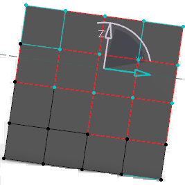
Vertex Selection Selects vertices only. The origin of the Robot is defined.

Select Using the Shift Key

You can propagate the selection of geometric elements (vertices, edges or faces) using the Shift key.

Let's take an example with edges.

  1. Select the first edge.
  2. Press Shift.
  3. Move the pointer over the mesh.
    A path of connected edges between (and including) the first selected edge and the edge under the pointer is computed and all edges in this path are highlighted. As you keep moving the pointer, the path is always recomputed between the two edges.
  4. Click to select the second edge.
    The optimum path between the two edges is chosen. All the edges selected in the path can be modified:

    The path is computed based on the following criteria:

    • If you select a free edge as the first edge, the preference is given to free side edges:

    • If you select an edge with weight, but not sharp, the preference is given to the weight edges:

    • If you select a sharp edge, the preference is given to the sharp edges:

    • If the first selected edge does not meet the above criteria, the shortest cumulative length or the smallest number of edges is defined.

    Important:
    • When there is more than one path for the selected edges, the first path found is highlighted.
    • When using Shift, two types of selections are available:
      • Trap Selection: this mode is activated when you press Shift and you drag the pointer before releasing Shift.
      • Range Selection: this mode is activated when you press Shift without moving the pointer before releasing Shift. This mode is available only to select edges. To compute the path, the trap selection mode is used.
    • The help text shows the selection mode.

Use Specific Colors

You can select elements using specific colors for the selected elements.

You can select and set the color in which the selected elements should be displayed.

Select the Use specific color for all selected elements check box in Me > Preferences > Shape > Imagine & Shape > Display > Performance tab. In the Specific color for selected element drop-down list, select the color. You can see that the selected elements are displayed in the color specified:

Edge selection

Vertex selection

Invert the Selection

You can invert the selected elements.

  1. Select one or more elements.


  2. Click Selection Inversion .
    Deselected elements become selected and vice-versa.

    Important: When All Type Selection is selected, all inverted elements are converted into vertices. Therefore the result of the inversion only contains summits.