Insulating Structure Panels | ||||||
|
| |||||
- Activate a physical product or a 3D shape representation to be used as a context.
- If the context is a physical product, a separate insulation 3D part with insulation feature, is created for each selected support.
- If the context is a 3D shape representation, insulation feature is directly created under the representation.
-
From the Structure Insulation section of the action bar, click Structure Panel Insulation
 .
.
-
In the Structure Panel Insulation panel,
select a PLM type from the list.
Note: The PLM type list is available only for physical product context.
-
Enter the name of the insulation feature.
You can keep the default name derived automatically.
-
In the Support box, select panels or plates to insulate.
You can select another insulation to create insulation over it.
- Optional:
Click Combine/Separate
 to combine the
insulations of the adjacent panels or plates.
In the Element List, the first panel is used as a reference for creating the insulation. The
 icon is displayed
in front of it. The insulation is created taking into account the properties of this
reference panel only.
 You can select a different panel and click Set as Reference
 to set it as a
reference. The panel is moved to the top in the list and set as a reference for
insulation creation.Notes:
to set it as a
reference. The panel is moved to the top in the list and set as a reference for
insulation creation.Notes:- A single insulation feature is created for the combined insulations.
- By default, the Combine/Separate
 button
is turned off and a separate insulation is created for each selected panel.
 - If some panels are not connected to the reference panel, an error message appears and such panels are removed from the selection.
- After splitting a combined insulation, the newly created insulations have the same properties as that of the combined insulation.
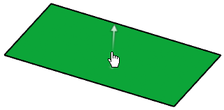
- Optional: Click the insulation orientation handle to switch the insulation side.
 The insulation is created on the other side of the plate.
 - Optional:
Select the Insulate both sides
check box to create insulation on both sides of the panel.
Two separate insulation parts are created in the tree.
- Optional:
Under Limits,
specify limits for the insulation.
- Select a reference plane, a surface, or a structural object to limit the insulation area.
- For the added limits, enter the offset values and invert the orientation if required.
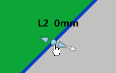
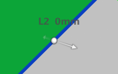
Tip: You can also change the offset and the orientation using handles. Offset handle Orientation handle 

- Under Material & Thickness, specify the material and thickness for the insulation.Note: If a material table is set in Data Setup, the materials appear in the Material list. Otherwise, you can click More... to import or search, and select the required material.
- Click OK.The insulation is created.
- To edit the insulation, select the insulation feature and click Edit Panel Insulation
 on the context toolbar.Notes:
- A proper context must be active.
- In physical product context,
- You cannot edit an insulation feature which is created under 3D part other than insulation 3D part.
- You cannot edit an insulation feature, if there are multiple insulation features created under the same insulation 3D part.
- The PLM type list is unavailable in edit mode.
- To extend the panel insulation edges, do the following:
- Select the panel insulation and click Extend Panel Insulation
 on the context toolbar.All the panel insulation edges are listed in the Insulation Edge Extender panel.
 - Select the Extend check box for the required edges, and then specify the height and angle values.
Note: The broken extensions that do not have proper support are deactivated and not listed in the Insulation Edge Extender panel. You need to delete such extensions manually. - Select the panel insulation and click Extend Panel Insulation