Insulating Structure Profiles | ||||||
|
| |||||
-
From the
Structure Insulation section of the
action bar,
click
Structure Profile Insulation
 .
.
- Optional:
Click Combine/Separate
 to
combine the insulations of the profiles whose traces are connected in G0
continuity.
to
combine the insulations of the profiles whose traces are connected in G0
continuity.
In the Element List, the first profile is used as a reference for creating the insulation. The
 icon
is displayed in front of it. The insulation is created taking into account the
properties of this reference profile only.
icon
is displayed in front of it. The insulation is created taking into account the
properties of this reference profile only. You can select a different profile and click Set as Reference
to
set it as a reference. The profile is moved to the top in the list and set
as a reference for insulation creation.Notes:- A single insulation feature is created for the combined insulations.
- By default, the Combine/Separate
button is turned off and a separate insulation is created for
each selected profile.
- If some profiles are not connected to the reference profile, an error message appears and such profiles are removed from the selection.
- For stiffeners on free edges created on multiple panels, the profile insulation considers the thickness of the reference panel only.
- The Support panel of stiffener check box in preferences must be selected if it was selected while creating the stiffeners.
- After splitting a combined insulation, the newly created insulations have the same properties as that of the combined insulation.
-
Under Contour Definition, select one of the following
contour types:
Contour Type Description Bounding box Insulation is created using the bounding box of the profile. 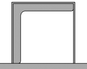
You can change the slope angle for insulation over stiffeners.
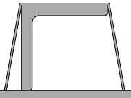
Section Insulation is created using the section of the profile. 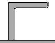
Formed shape Insulation is created with a formed shape. The shape is computed using the T1, T2, W, h1, and h2 parameters. 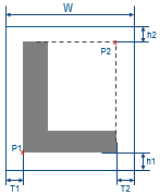
You can do any of the following:
- From the Mode list, select any of the following combinations and specify the values of the parameters to compute the shape: T1 + T2, T1 + W, or T2 + W.
- Click ƒx Thickness to link the parameters to the profile thickness and compute the shape automatically using a formula. In case of a combination that includes W, you need to specify the value of W.
For stiffeners, you can specify the value of the h2 parameter as zero.
Result:
Tip: Specify a value in the Extend length box to extend the length of the profile insulation, to strengthen its connection with the panel insulation. This box is unavailable for the Formed shape contour type. - Optional:
To edit the insulation, select the insulation feature and click
Structure Profile Insulation
on the
context toolbar.
Notes:
- A proper context must be active.
- In physical product
context,
- You cannot edit an insulation feature which is created under 3D part other than insulation 3D part.
- You cannot edit an insulation feature, if there are multiple insulation features created under the same insulation 3D part.
- The PLM type list is unavailable in edit mode.