About the Surfacic Contact Model | |||||||
|
| ||||||
Elastic Properties
The behavior of bodies during and after contact depends on the elastic properties of the materials.
| Property | Description | Default value |
|---|---|---|
| Damping Coefficient | Attenuation coefficient of the penetration. | 2.e9kg/m²/s |
| Damping Transition Depth (optional) | Application thickness of the damping force. | 0.1mm |
| Important: Before launching a dynamics simulation, specify a mass and an inertia for every body that is not fixed. |
| Property | Description | Default value |
|---|---|---|
| Young Modulus | Physical property measuring the stiffness of a solid material. | 210 GPa (steel pressure) |
| Poisson's Ratio | Ratio of the transverse strain to the longitudinal strain in an elastic body under longitudinal stress. | 0.3 (no unit) |
| Stiffness | Extent to which an object resists deformation in response to the penetration. | Value obtained by dividing the physical properties of the material (K) by the
Elastic Layer Thickness (b): c = K/b |
| Elastic Layer Thickness | Application thickness of the elastic force. | 5mm |
Specify the Young Modulus, Poisson Coefficient, and Elastic Layer Thickness for each group of collidable bodies.

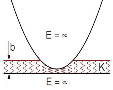
This illustration represents the elastic layer thickness (b), the physical property of the material (K), and the Young Modulus (E) during a contact.
To reduce the stiffness (c = K/b), you can increase the value of the elastic layer thickness.
Force Properties
Following the contact, the dynamics solver generates and applies a force on the contact areas. The force is composed of a Normal Force (Fn) and a Tangential Force (Ft).
The Normal Force is the sum of both the Elastic Force and the Damping Force: Fn = Fe + Fd
The Elastic Force (Fe) is the force resisting the stretch or compression of material.
Fe = c.A.u, where
- c is the stiffness.
- A is the contact area.
- u is the penetration.
The Damping Force (Fd) is the force that opposes the relative motion between interacting surfaces.
 , where
- d is the surfacic damping.
- A is the contact area.
- vn is the penetration velocity.
- ud is the damping transition depth.
The Tangential Force (Ft) is the force acting on a moving body in the direction of the tangent to the curved path of the body. As a consequence, the velocity of the body diminishes or increases.
![]() , where
, where
- μ is the friction coefficient.
- ve is the friction velocity
- vt is the tangential velocity.
Friction Properties
Friction includes the static friction between nonmoving surfaces, and the kinetic friction between moving surfaces.
Friction between two bodies is represented by a regularized modeling of the Coulomb model, and is proportional to the speed of the body.
| Property | Description | Default value |
|---|---|---|
| Friction Coefficient | Ratio of the friction force between two bodies and the force pressing them together. | 0.4 (no unit) |
| Friction Velocity | Shear stress characterized with a velocity unit. | 10mm/s |
The accuracy of the simulation results depends on the order of selection of the bodies. The first selected element in Group1 is considered as the main body, and the others as secondary bodies.
Select the body with the highest tessellation as the main body to obtain a more accurate simulation.
Meshing Properties
The surfacic contact model requires a tessellation high enough to obtain accurate meshing results. You can use visualization meshes (default tessellation) or compute meshes to specify a higher tessellation. For more information on meshing, see Managing Contacts.
| Property | Description | Default value |
|---|---|---|
| Max Penetration | Maximum penetration depth for a realistic contact. | 5mm The value corresponds to the value of the Elastic Layer Thickness. |
| Chordal Deviation | Perpendicular distance between the actual curve and the approximating line segments. | 0.5mm |
| Triangle Size | Max edge length of the triangle elements generated by the mesher. | 2mm |
The Max Penetration value determines the maximum penetration depth possible to obtain a realistic contact during the simulation. If the max penetration value is exceeded, the penetration occurs between the bodies with no reaction force.
| Important: Specify the Max Penetration value according to the size of the mechanism's products, and to the range. |
The Max Penetration value must be high enough to detect correctly the contact corresponding to the surfacic model parameters and the user parameters, or the contact is missed. The surfacic contact model allows penetrations according to different parameters (ex: stiffness, damping, user parameters).
You can manage the accuracy of the mesh in the 3D area by accessing theCommon Preferences of the 3DEXPERIENCE Platform. It is recommended to use the default Fixed option depending on your objective:
- Visual quality of the mesh: It is recommended to use the Fixed option with a SAG value of 0.5 to obtain a very precise mesh.
- Simulation performance: It is recommended to use the Fixed option with a value lower than 0.5 to obtain a lighter mesh (due to a less precise mesh).
The 3D accuracy option impacts the contact detection as it relies on the tessellated
geometry of the model and not on the exact geometry. Contacts are not detected if the
tesselated objects are not in contact. However, the app computes
contact meshes from exact geometries, and based on the parameters defined in the
Contact Connection![]() dialog box.
dialog box.