Smart Positioning 3D Parts

Taking advantage of published geometry, you can smart position 3D parts by dragging the part you want to place.

Published geometry is used to infer and identify the most appropriate relationships and the best fit solutions. Lines, planes, points and axis systems are suitable elements for publication.

Tip: From the Tools section of the action bar, click Publish to publish geometry.


Before you begin:
  • The two 3D parts you want to position must contain published geometry.
  • Select the parent structure level containing the two 3D parts. For more information, see Basic Concepts.
See Also
Smart Positioning Illumination System Parts
Mating the Illumination System to the Microscope
Snapping 3D Parts into Position
  1. Start to drag the part you want to place, then release the left mouse button.
    The part you want to place is attached to the pointer.

  2. Move the mouse pointer over the geometry of the second part.
    A tooltip is displayed in the top-right corner indicating the number of solutions found based on the published geometry of both parts. As you move the mouse pointer over the geometry, the preview snaps into place when a potential solution is found and the pointer changes to show the engineering connection type.

    The best fit solution based on the published geometry of both parts and the position of the pointer is proposed.
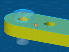
    Available engineering connection types are:

    Revolute
    Cylindrical
    Planar
    Rigid
    Spherical

  3. Optional: If the smart position is not the one you are looking for, continue to move the mouse pointer over the geometry of the second part.

    Alternatively, press Page Up or Page Down to visualize the other solutions proposed.

  4. When the smart position is satisfactory, click to validate.
    The two 3D parts are mated together.

    An engineering connection defining constraints is created and the corresponding constraint symbol is displayed. For more information, see Assembly Design User's Guide: Engineering Connections.


  5. Optional: To edit the constraint you have just created, click the constraint symbol and do one or more of the following:
    • Select the constraint mode: driving , measured or controlled .
    • Select the constraint orientation for one or both 3D parts: undefined , same , opposite or parallel .
    • Select De-activate to de-activate the 3D constraint.
    • For angle and distance constraints, change the value.

    Tip: To show callouts identifying connected 3D parts and context toolbars when editing engineering connections, select Display in geometry area in Me > Preferences > Mechanical > Natural Assembly.