-
In the 3D view, select an equipment center.
A context toolbar appears. 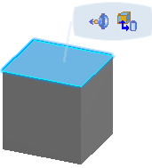 -
Click Create 3D Allocation
 . .
The 3D Allocation dialog box appears. The name of the equipment center is in the Name area of the dialog box.
- Optional: Click Show or Hide Command Dialog
 to hide the dialog box. to hide the dialog box. -
In 2D graph,
select a logical component.
You can only select a component that is not already allocated to the equipment center. - The name of the logical component appears in the Associated Logical Objects area of the dialog box.
- If a 3D shape is associated to the logical component, the shape is highlighted and a dotted line links the shape with the equipment center.
- Optional: To remove a component from the list in the dialog box, click the name in the Associated Logical Objects area of the dialog box.
The component is removed from the list. - Optional: To allocate more logical components to the equipment center, select the logical components.
The names of the components are added to the list in the dialog box. -
When finished, click Close to exit the command.
- In the tree or 2D graph, click the component you have just associated to the equipment center.
- In the 3D view, the component is highlighted, the associated equipment center is highlighted and a dotted line links the two.
- In the tree, the associated equipment center is highlighted.
|