Creating a Pathway | |||
| |||
- From the Pathway section of the action bar, click Create Pathway
 .
.A context toolbar appears.
A pathway set is added to the tree under the active system or subsystem. It contains one pathway and one segment. The pathway set name is automatically generated by the system (however you can modify the name; right-click the name in the tree and select ).

- Optional: To set options for the pathway, click
 in the context toolbar.The Pathway Options dialog box appears.
Define your options and then click Close.
- Optional: To set offset options, in the context toolbarclick
 .The Define offset mode and offset value dialog box appears.
Define your options and then click Close.
If necessary, you can reopen this dialog box at any time while you are creating the pathway.
- In the context toolbar, select a point positioning mode:
 Basic Creation Mode: Move the pointer in the work area; it will detect Pathway Branch Points,
Pathway Connection Points (PCP), 3D points, and points and surfaces on 3D shapes. Hold down Ctrl to create passing points offset from a shape. To reverse the offset direction, also hold down Shift.
Basic Creation Mode: Move the pointer in the work area; it will detect Pathway Branch Points,
Pathway Connection Points (PCP), 3D points, and points and surfaces on 3D shapes. Hold down Ctrl to create passing points offset from a shape. To reverse the offset direction, also hold down Shift. Key-in XYZ Coordinates: Enter your own x, y and z coordinates for a point.
 Route along robot base plane: Click in the work area to place a point on the robot base plane. Reposition the robot to change the base plane if necessary.
 Create New Point using Robot: Drag the robot; when you release, a point is created.
- Use the point positioning mode selected (or a combination of any of the modes) to create the pathway, going from point to point.
Tip: In order to connect to a shape at each end of the pathway, use Basic Creation Mode or Create New Point using Robot for the start and end points. You can use these or any of the other point positioning modes for the intermediate points.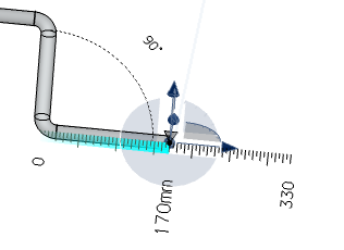 Note: A length ruler is displayed to show the current length of the pathway. You can change the length value by clicking on it. If you bend the pathway, an angle ruler is also displayed.
 - When you have finished your pathway, in the context toolbar click Exit Command
 .The pathway is created.
Important: If a shape at the end of a pathway is subsequently moved (using the Robot), the pathway will adjust automatically to the new position of the shape during an update. Note: To delete a pathway, select the pathway and press the Del key. The pathway is automatically deleted if the representation is fully loaded. When the representation is not fully loaded, the Pathway Deletion dialog box appears.You can choose to load the representation or to delete the whole pathway set.