Handling Annotation Leaders | |||||||
|
| ||||||
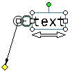
- Right-click the yellow control point at the end of the
leader.
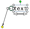
- Select from the available options.
Note: Multi-selection is not taken into account for these options, except for Symbol Shape. The operation is performed only on the leader you right-click in the selection.
To make another selection, choose Other Selection. In the window that appears, select another element.
Perform various operations on the leader using the following table:
Operation Command Result To add a breakpoint on the leader Select Add a Breakpoint. 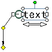
To remove a breakpoint Select Remove a Breakpoint. To add an extremity to an existing breakpoint (for texts or welding symbols only) Select Add an extremityand then click where you want to position the extremity. 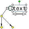
To remove an extremity Right-click the additional extremity and select Remove Leader/Extremity. Note: Clicking on the main leader extremity will remove the leader itself.
To add an interruption Select Add an Interruption and then, on the leader, click the two points between which you want to add the interruption. 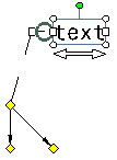
To remove an interruption Right-click the leader yellow control point and select Remove Interruptions. Important: Any existing interruption will be removed from the leader when adding or removing breakpoints. To remove the leader Select Remove Leader/Extremity. 
To add an application zone symbol Point to Application Zone . Then select No Zone, if you do not want a symbol, or select the required symbol from the following available symbols: - Global All Around
- Partial All Around
- Global All About with horizontal axis indicator
- Global All About with vertical axis indicator
- Partial All About with horizontal axis indicator
- Partial All About with vertical axis indicator
- Global All Over
- Partial All Over

These symbols are used to specify that a specification is to be applied all around, all about or all over the 3D profile of a part. You can also specify whether it is to be applied globally or partially. This complies with ISO, JIS and ASME international standards.
Notes:- When you update the earlier standard, the display of all around and all over symbols changes according to new standard specification.
- The anchor symbol is not available on additional extremities.
To modify the leader symbol shape Point to Symbol Shape. Then select No Symbol if you do not want a symbol for the leader, or select the symbol you want from the available symbols. Important: Changing the symbol shape behavior differs depending on whether one or several annotations in the selection have more than one leader: - If the leader you right-click is the only one in the annotation, then the symbol is applied to this leader and to all annotations which have only one leader.
- If the leader you right-click is not the only one in the annotation, then the symbol is applied to this leader only.
To add an extremity link Select Add Extremity Link and then select a reference. It creates a positional link with respect to the selected reference. If you press Ctrl, an orientation link is created. To replace the extremity link Right-click the yellow control point and select Extremity Link > Replace and then select another reference element. The extremity link is replaced.
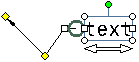
To remove the extremity link Right-click the yellow control point and select Extremity Link > Remove. The extremity link is removed. To make the extremity link perpendicular Right-click the yellow control point and select Extremity Link > Perpendicular. The extremity link is made perpendicular with respect to the reference it is attached with. - Move the leader or any existing breakpoints
by clicking a yellow control point and moving it using the pointer.
-
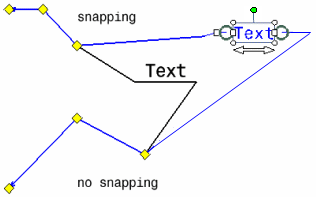
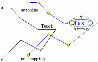
To move the annotation but not the leader, click the annotation and move it using the pointer.
-
To move the leader along with the annotation while making sure the leader keeps its original shape, select Rigid and then move the annotation.
Important: - This functionality is available for texts, welding symbols, 2D components, tables and geometrical tolerances, but not for other annotation types.
- This functionality also applies when rotating the annotation text using the rotation handle.
-