Creating/Modifying Coordinate Dimensions

You can automatically create 2D or 3D coordinate dimensions on elements and define the display format of coordinate dimensions. Coordinate dimensions let you define the coordinates of a point relative to the X, Y, and possibly Z, axes.

This task shows you how to:


Before you begin: Open a drawing representation containing geometry.

Creating Coordinate Dimensions

You can create coordinate dimensions.

  1. From the Annotation section of the action bar, click Coordinate Dimension .

    In the Tools Palette, the following options are available:

    • 2D Coordinates lets you create 2D (x, y) coordinate dimensions for interactive geometry.
    • 3D Coordinates lets you create 3D (x, y, z) coordinate dimensions for generative geometry.
      Important:
      • These options are also available through the context menu.
      • This choice of options is valid for generative geometry only. In the case of a generative drawing, or in the case of a drawing containing a mix of generative and interactive elements, both options are available. But if you select sketched (i.e. interactive) geometry, the 2D Coordinates option is applied automatically (even if you selected the 3D Coordinates option). In the case of a purely interactive drawing, the options are not displayed at all, and only the 2D Coordinates option is applied.

  2. Select 3D Coordinates to dimension elements generated from the 3D.
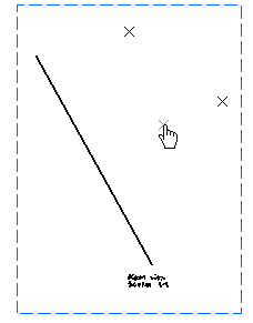
  3. Select the element for which you want to create the 3D coordinate dimension.

    The coordinate dimension is created.


    Important:
    • At this point, you can right-click to display the context menu, which allows you to add a breakpoint to the leader, or to choose the leader symbol.
    • You can also select a set of elements by trapping them with the mouse, to create several coordinate dimensions in one shot.
  4. Click in the sheet to position the dimension.
  5. Click the coordinate dimension to modify its position.
  6. Drag the dimension or the yellow handle to a new position.


    Important:
    • Coordinates are relative to the absolute axis system except for views created by selecting a 3D local axis system.
    • The yellow anchor point is associative and is linked to the element you dimensioned.
    • If you create a coordinate dimension on the origin, this dimension is invariably non-associative. In this case, the leader symbol may be different from the leader symbol used for associative coordinate dimensions. For more information, see Dimension Styles.
  7. Click anywhere in the sheet to validate.


Modifying Coordinate Dimension Value Display Format

You can modify coordinate dimension value display format.

Before you begin: Create a coordinate dimension.
  1. To modify the coordinate dimension value display format, right-click the coordinate dimension and select Properties.
  2. In the Properties dialog box, under Numerical tab, the display format can be changed.

    Format: You can set the required format.

    • Description: Select a type of format. To get the detailed description about the format selected from the list, click the information point .
      Important: The Description standard and its format values can be customized by the administrator in Dimension Value Formats (Me > Preferences > Standards > [standard name] > Value Formats).
    • Display: Depending on the selected format, you can choose to display one, two or three factors.
    • Format: Only decimal format available.
    • Precision: Select the value precision.
      Important:
      • The properties of the display value format can be configured by the administrator in Dimension Styles (Me > Preferences > Standards > [standard name] > Value Display Format).
      • If new styles have been defined by the administrator in Me > Preferences > Standards for this type of element, then they are displayed in the Style list. The properties of the element can be changed by selecting another style from the list.

  3. Select description as FEET-INC and display as 2 factors and then click OK.

    The coordinate dimension display value is changed.

    If only the description format name and precision value is to be changed, then you can use Numerical Properties and select from the list.


    Important:
    • Each coordinate dimensions can have different display parameters (format description, precision value, etc.).
    • The Display Units option (by right-clicking and selecting Properties > Text, tab) is available for only those pre-R18 coordinate dimensions that do not have format information.
    • When the given format name is not valid (i.e. does not correspond to an existing value format description or left blank), then the coordinate dimension on which the style is applied or the NUM.DIMM format, or the first allowed in the Allowed Numerical Formats will be applied.
    • For pre-R18 drawings:
      • If the option Use style values to create new objects is selected in Me > Preferences > App Preferences > 3D Modeling > Mechanical Systems > Drafting > Administration expander, the description information is not set and the resulting coordinate dimension follows the old display.
      • If this option is cleared the value available in the Numerical Properties is used.