-
Double-click the right view to activate it.
Note:
The silhouette edge will be projected in the current
view.
-
From the Sketch section of the action bar click Project 3D Canonical Silhouette Edges
 . .
-
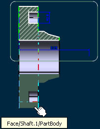
In the 3D background of the section view, select the
canonical surface (cylinder, sphere, torus) to be projected. Its axis
must be parallel to the view plane.

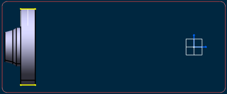
The silhouette edge is projected onto the right view
plane.

-
Optional:
Deactivate Display Backgrounds as Specified
for Each View
 to view the projected silhouette edge without the 3D background.
|