- From the View Layout section of the action bar
, click
Principal Views
 . . - Select a face of the 3D representation.
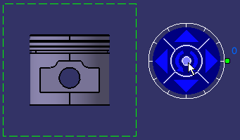
- Click the right or left arrow on the robot to visualize the
left or right side, respectively.
- Click the top arrow to visualize the bottom side.
- Click the counterclockwise arrow to rotate the reference
plane.
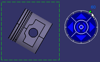
- Drag the green knob to redefine the rotating angle.
The default
increment value is 30 degrees.

- Right-click the knob and select the required option to modify the increment value.
-
Free hand rotation: Lets you rotate the knob
in a free manner using the mouse, instead of snapping it to a given increment.
-
Incremental hand rotation: Snaps the rotation
to a given increment (from 30 to 30 degrees, between zero and 330). This
is the default value.
-
Set increment...: Displays the Increment
Setting dialog box. Enter the required value in the Increment
value box. For example, type 5 deg (for 5 degrees) and click
OK.
-
Set current angle to:
-
0 deg: Sets the current angle value to 0 degree.
-
90 deg: Sets the current angle value to 90
degrees.
-
180 deg: Sets the current angle value to 180
degrees.
-
270 deg: Sets the current angle value to 270
degrees.
-
Set angle value...: Displays the Angle
Setting dialog box. Enter the required value in the current
angle (deg) box.
- Click on the center of the robot to set the position of the
view.

The view is created.

|
