From the Connections section of the action bar,
click Tie Detection.
Choose the Search domain using one of the following
methods:
Select the entities directly from the 3D view or the model tree.
Select one of the following from the context menu:
Option
Description:
All 3D part bodies
Includes the main PartBody in the search domain, including all 3D
geometry. This is the default search domain.
Meshed supports
Includes only the parts that are already meshed in the search domain.
Note:
After you use this option, you can select additional features from the
model; these features are appended to the list.
Warning:
When calculating the distance between surfaces for 2D meshes, the search
considers the part thickness (as defined in the shell section). This
thickness is projected in all directions, not only along the surface
normals, so tie detection might find some face pairs that are further apart
than the search tolerance.
All geometries
Includes 2D and 3D features from ordered geometrical sets in the search
domain, in addition to the regular 3D geometry.
Tip:
You can use the context menu to review and edit the list of features included in the search domain.
Optional: Change the Search tolerance.
This value defines the maximum separation distance between surface pairs to be tied
together.
From the Detect interactions on options, select
Simple or Hybrid.
Option
Description
Simple
Select one of the following options:
Geometry: Searches for tie locations on geometry
only.
Mesh: Searches for tie locations on meshes only. Both
native and orphan meshes are considered.
Hybrid
Select one or more of the following options:
Geometry: Searches any geometry already included in the
search domain.
Native mesh: Searches any native meshes already included
in the search domain.
Orphan mesh: Searches any orphan meshes already included
in the search domain.
Optional:
If the search includes meshes, you can specify an angle by which to extend the meshed
faces. The default Extend by angle is 10 degrees.
The example below shows a potential tie pair, including the effects of the
Extend by angle option.
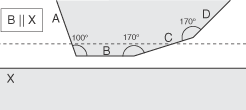
Mesh surfaces B and X (represented in two dimensions) are parallel and lie within the
tie detection distance (Search tolerance) represented by the
dashed line. The adjacent surfaces A, C, and D are attached to B at the given angles. By
default (without the Extend by angle option), a tie pair is
created for B and X. If you set the Extend by angle option to 10
degrees, surface B is extended to include surfaces C and D. The Extend by
angle tolerance is checked at each surface boundary and does not limit the
total angle relative to the original surface. Surface D is included, even though it lies
beyond the search tolerance, because it is now considered to be an extension of surface
B.
Optional:
Preselect the following default options for the tie connections:
Option
Description
Tie rotational DOFs if applicable
Tie rotational degrees of freedom in addition to the translational degrees of freedom.
Adjust secondary surface initial position
Move all tied nodes on the secondary surface onto the
main surface in the initial configuration, without any strain.
You can edit and change any of the candidate tie features before they are
finalized.
From the Engineering connections creation options, select one of
the following:
Option
Description
One for all connection properties
Creates a single engineering connection for all detected tie
connections.
One per connected parts
Creates or selects engineering connections based on which parts are
connected.
One per connection property
Creates an engineering connection for each different connection
property.
Click Find Ties.
A separate dialog box shows the tie detection progress. When completed, a table displays the candidate tie features for surface pairs that meet the detection requirements.
You can right-click any row in the table to Locate,
Edit, or Remove that tie feature. You
can also choose Invert Selection to select the other tie features
in the table.
In addition, you can [Ctrl]+[Click] or
[Shift]+[Click] to select multiple rows in the table and then
choose Edit or Remove Selected for
those features. Again you can choose Invert Selection to select
the other tie features in the table.
If you select Edit from the context menu, the Tie Candidates dialog box opens to let you enter or change parameters for all of the
selected features. These options are described in Defining Ties.
Optional:
Repeat steps 2 and 3, then click
Find Ties again to search for additional surfaces to tie.
When you run tie detection, the tool does not create a tie pair if that pair was
previously created. This is to prevent duplicate pairs.
Locations found using the changed options are added to the table. New matches
are marked with an asterisk (*). You can modify the new selections as described
above.
To create all of the listed tie features, click OK in the dialog box.
To edit any of the tie connections after they have been created, double-click on its glyph in the model or on its name in the Feature Manager.
The Feature Manager can also be used to locate or delete a tie.