-
Double-click the Front View.x to activate it.
-
From the Review section of
the action bar, click Flag Note with Leader
 . .
-
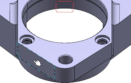
Select a face to position the arrow end of the leader.

Notes:
- A number is displayed in the Name box and this
number is incremented each time you create a flag note. You can also
modify this string.
-
 Hyperlinks
opens the Hyperlinks dialog box.
-
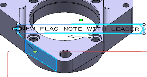
Position the annotation at the required location.
Note:
Press Ctrl to position the annotation according to
the pointer, if the Allow to indicate annotation body position
(CTRL toggles) check box is cleared in the preferences.
-
In the Flag Note
Definition dialog box, enter the required text.
-
Click OK.
The flag note (identified as Flag Note.xxx) is added to the tree under the Note sub-node.  -
Optional: Move the leader so that the leader extremity is snapped
on the privileged direction.
The privileged directions are horizontal, vertical, reference normal and
reference tangent directions.
-
Click in the 3D area.
-
Right-click the annotation flag note with leader and select Switch
to 3D Leader to make the 2D leader a 3D leader.
The diamond at the arrow end of the leader becomes
parallel to the screen. Based on the preferences specified you can modify the
position arrow end of the leader. For more information, see Annotation Default Position Along View Normal
.
|