This problem illustrates the use of the smeared crack model in
Abaqus/Standard
and the brittle cracking model in
Abaqus/Explicit
to model reinforced concrete, including cracking the concrete, rebar/concrete
interaction using the “tension stiffening” concept, and rebar yield.
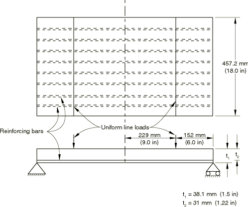
The structure modeled is a simply supported slab, reinforced in one
direction only. The slab is subjected to four-point bending. The local energy
release and the concrete-rebar interaction that occur as the concrete begins to
crack are of major importance in determining the structure's response between
its initial, recoverable deformation and its collapse. The problem is based on
an experiment by Jain and Kennedy (1974) and has been analyzed numerically by
others (Gilbert and Warner, 1978, and Crisfield, 1982).
The dimensions of the slab and the layout of the reinforcements are shown in
Figure 1.
The symmetry of the problem suggests that only half the slab needs to be
modeled.
We assume that the response is essentially one-dimensional but model the
slab in
Abaqus/Standard
as a beam, as a shell, as a continuum, and as a continuum shell to provide
verification of the reinforced-concrete modeling capabilities. The response
will be uniform in the central section of the slab, so a simple mesh will
suffice. The beam and shell models use five elements in the half-slab. The
number of concrete integration points through the thickness of the slab is set
to nine instead of the default of five points. This provides a smoother
response as the cracks propagate through the thickness.
The solid element models use second-order elements or reduced-integration
linear elements, because this is a bending problem and the first-order fully
integrated elements do a poor job of modeling bending. Two second-order
elements are used through the thickness of the slab so there will be enough
stress calculation points through the thickness for the response to be
reasonably smooth (as in the beam and shell models). Five elements are again
used along the half-slab. Because bending is the primary mode of deformation, a
minimum of four reduced-integration linear elements (C3D8R or CPS4R) are needed through the thickness of the model to capture the
response adequately. Four different CPS4R meshes are used to assess the sensitivity of the results to mesh
refinement: a 4 × 10 mesh, a 4 × 20 mesh, an 8 × 10 mesh, and a 4 × 40 mesh.
Material
The material properties are taken from Gilbert and Warner (1978) and are
shown in
Table 1.
The concrete cracking model in
Abaqus/Explicit
allows unlimited strength in compression. This is a reasonable assumption in
this problem, because the behavior of the structure is dominated by cracking
due to tension in the slab under bending.
The effects of the concrete rebar interaction and the energy release during
cracking are modeled indirectly in
Abaqus
by adding tension stiffening to the plain concrete model, as illustrated in
Figure 2.
This approach is described in detail in
An inelastic constitutive model for concrete
and
Concrete Smeared Cracking
for
Abaqus/Standard
and in
A cracking model for concrete and other brittle materials
and
Cracking Model for Concrete
for
Abaqus/Explicit.
The simplest tension stiffening model, a linear reduction in the tensile
strength beyond cracking failure of the concrete, is used in this problem,
following Crisfield (1982). To illustrate the effect of tension stiffening
parameters on the explicit dynamic response, three different values (5 ×
10−4, 8 × 10⁻⁴, and 11 × 10−4) are used in the
Abaqus/Explicit
analysis for the strain beyond failure at which all the tensile strength of the
concrete is lost. The
Abaqus/Standard
analysis uses a value of 5.7 × 10⁻⁴ (about 10 times the failure
strain), a typical assumption for standard reinforced-concrete designs that
gives a reasonable match to the experimentally measured response of the slab.
For illustration purposes the
Abaqus/Standard
analyses are also run without tension stiffening effects, although this is not
recommended as a model for practical cases.
Since the explicit dynamic problem involves pure bending, the response is
controlled by the material behavior normal to the crack planes. The material's
shear behavior in the plane of the cracks is not important. Thus, the choice of
shear retention in
Abaqus/Explicit
has a minimal influence on the results, provided that a reasonable value is
used. We have chosen to use a shear retention that is exhausted at a value of
crack opening that is 100 times the value at which the tension stiffening is
exhausted.
Solution control parameters and loading
Reinforced concrete solutions involve regimes where the load-displacement
response is unstable. The Riks procedure in
Abaqus/Standard,
described in
Modified Riks algorithm,
is designed to overcome difficulties associated with obtaining solutions during
unstable phases of the response. It assumes proportional loading and develops
the solution by stepping along the load-displacement equilibrium line with the
load magnitude included as an unknown. When the Riks method is used, the
relative magnitudes of the various loads given on the data lines specify the
loading pattern. The actual magnitudes are computed as part of the solution.
The user must prescribe loads and provide solution parameters that will give a
reasonable estimate of the initial increment of load. If the response is
linear, this first increment of load will be the ratio of the initial time
increment to the time period, multiplied by the actual load magnitude. If the
response is nonlinear, the initial load increment will be somewhat different,
depending on the degree of nonlinearity. The termination condition for the
analysis is set in this case by specifying a maximum required displacement in
the middle of the step as 9 mm (.35 in). This is enough to ensure that a limit
condition is reached.
Since
Abaqus/Explicit
is a dynamic analysis program and in this case we are interested in a static
solution, care must be taken that the slab is loaded such that significant
inertia effects are avoided. For analyses such as this one, in which the static
load-displacement response is unstable, it may be difficult to avoid inertia
effects with a dynamic procedure if force-controlled loading is used (even if
the forces are ramped on slowly). Displacement-controlled loading is often a
viable alternative. In this problem the slab is loaded by applying a velocity
that increases linearly from 0.0 to 5.0 in/second over 0.1 seconds. This
loading causes a midspan deflection of approximately 0.3 in. The loading is
slow enough to ensure that quasi-static solutions are obtained.
The boundary conditions are symmetric about (all nodes along have prescribed) and, for the
C3D8R models, symmetric about −1.5 in (all nodes along −1.5 in have prescribed). All the nodes along the bottom edge ( −0.75 in) at 15 in have .
Results and discussion
Results for all analyses are discussed in the following sections.
Abaqus/Standard
results
The
Abaqus/Standard
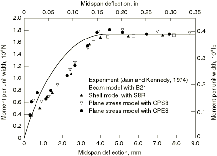
analyses are compared with the experimental response on the basis of the
deflection at the middle of the slab plotted versus the moment per unit width
on that section of the slab.
Figure 3
shows the analyses that do not include tension stiffening, and
Figure 4
shows those that do include tension stiffening in the manner described above
for the beam, shell, and continuum models. The experimental data obtained by
Jain and Kennedy (1974) are also plotted on these figures. In the analysis
without tension stiffening the initial cracking of the concrete causes a loss
of strength in the slab, while the inclusion of tension stiffening eliminates
this drop in load even though the concrete is cracking. The cracks propagate
rapidly through the slab, until collapse occurs as the rebar yields. The
collapse load is well predicted by all the models, and the various geometric
models are reasonably consistent both with and without tension stiffening. The
improvement in predicting the actual response obtained from including tension
stiffening is obvious when the two figures are compared, graphically
illustrating the need for including this effect in the model.
The results for the continuum shell element analysis are similar to results
obtained from the S8R model.
Abaqus/Explicit
results
Figure 5
shows the 4 × 20 mesh that was used in the
Abaqus/Explicit
analysis.
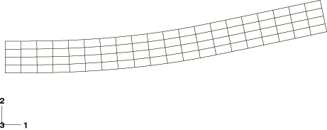
Figure 6
shows the deformed shape at
0.1, which is the point of full load application.
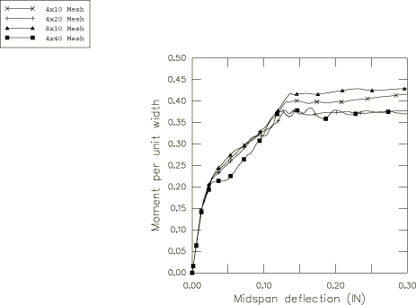
The load-deflection response of the slab for the four different mesh
densities using a tension stiffening value of 8 × 10⁻⁴ and CPS4R elements is shown in
Figure 7.
Meshes with 10 elements along the length predict a slightly higher limit load
than the mesh with 20 elements along the length. The mesh with 40 elements
along the length of the slab gives results that are nearly identical to those
given by the mesh with 20 elements. The tension stiffening study described next
is, therefore, performed using the 4 × 20 mesh.
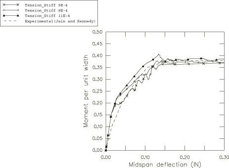
The results using the 4 × 20 mesh of CPS4R elements are compared to the experimental data in
Figure 8
for three different values of tension stiffening. It is clear that the less
tension stiffening used, the softer the load-deflection response will be during
the cracking of the concrete. The middle value of tension stiffening appears to
match the experimental data best. The load-deflection responses during the
latter part of the analyses are almost entirely governed by the yield in the
rebar and are, therefore, nearly independent of the tension stiffening.
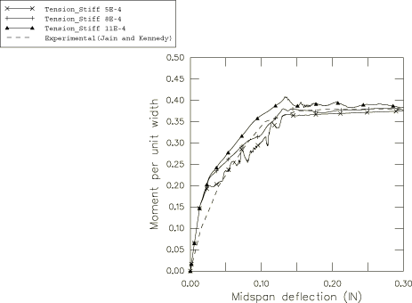
The results using the 4 × 20 mesh of C3D8R elements with the various values of tension stiffening are
compared with the experimental data in
Figure 9.
The results using a 2 × 10 mesh of S4R elements with the various values of tension stiffening are
compared with the experimental data in
Figure 10.
The results for both C3D8R and S4R elements are similar to those obtained with the CPS4R elements.
Slab modeled with 20 S4R elements (2 × 10 mesh) using a tension stiffening value of 11 ×
10−4.
References
Crisfield, M.A., “Variable
Step-Lengths for Nonlinear Structural
Analysis,” Report 1049, Transport and Road
Research Lab, Crowthorne,
England, 1982.
Gilbert, R.J., and R. F. Warner, “Tension
Stiffening in Reinforced Concrete
Slabs,” Journal of Structural Division,
American Society of Civil Engineering, vol. 104,
ST12, pp. 1885–1900, 1978.
Jain, S.C., and J. B. Kennedy, “Yield
Criterion for Reinforced Concrete
Slabs,” Journal of Structural Division,
American Society of Civil Engineering, vol. 100,
ST3, pp. 631–644, 1974.
Tables
Table 1. Assumed material properties for one-way slab. Reinforcement ratio
(volume of steel: volume of concrete) 7.2 × 10⁻³.
Concrete properties
Young's modulus:
29 GPa (4.2 × 10⁶
lb/in2)
Poisson's ratio:
0.18
Yield stress:
18.4 MPa (2670
lb/in2)
Failure stress:
32 MPa (4640
lb/in2)
Plastic strain at failure:
1.3 × 10⁻³
Ratio of uniaxial tensile to
compressive failure stress:
6.25 × 10⁻²
Density:
2400 kg/m3 (2.246
× 10−4 lbf s2/in4)
Cracking failure
stress:
2 MPa (290
lb/in2)
In the
Abaqus/Explicit
analyses “tension stiffening” is assumed as a linear decrease of the stress to
zero stress at a direct cracking strain of 5 × 10⁻⁴, 8 ×
10−4, or 11 × 10−4.
Steel (rebar) properties
Young's modulus:
200 GPa (29 ×
106 lb/in2)
Yield stress:
220 MPa (31900
lb/in2) (Perfectly plastic)
Figures
Figure 1. One-way reinforced concrete slab. Figure 2. Tension stiffening effect. Figure 3. Moment-deflection response with no tension stiffening (Abaqus/Standard). Figure 4. Moment-deflection response with tension stiffening (Abaqus/Standard). Figure 5. Undeformed CPS4R 4 × 20 mesh (Abaqus/Explicit). Figure 6. Deformed CPS4R mesh (Abaqus/Explicit).
Deformation is magnified by a factor of 5. Figure 7. Moment-deflection response of Jain and Kennedy slab; influence of mesh
refinement. CPS4R elements (Abaqus/Explicit). Figure 8. Moment-deflection response of Jain and Kennedy slab; influence of
tension stiffening on 4 × 20 mesh. CPS4R elements (Abaqus/Explicit). Figure 9. Moment-deflection response of Jain and Kennedy slab; influence of
tension stiffening on 4 × 20 mesh. C3D8R elements (Abaqus/Explicit). Figure 10. Moment-deflection response of Jain and Kennedy slab; influence of
tension stiffening on 2 × 10 mesh. S4R elements (Abaqus/Explicit).