Problem description
The basic constant parameters of the analysis models are as follows:
| Spring constant, k | 5253.8 N/m (30 lb/in) |
| Damping coefficient, c | 21.02 N/m-s (0.12 lb/in-s) |
| Mass, m | 4.536 kg (0.02588 lb-s2/in) |
SPRING1 and DASHPOT1 elements are used in analyses 1–3. SPRING2 and DASHPOT2 elements are used in analysis 4.
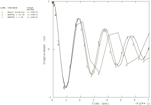
In analysis 1 the model is the one-degree-of-freedom system shown in Figure 1. The initial displacement is 25.4 mm (1 in), so the force in the spring is initially 133.4 N (30 lb). The problem is run in two steps: a static step, wherein the initial displacement is imposed, and a dynamic step, during which the structure is allowed to oscillate. The dynamic step is run with automatic time stepping, using two different values for the half-increment tolerance: 44.48 N (10 lb) and 4.448 N (1 lb). The higher value of the tolerance should give moderately accurate results, while the lower value should result in a more accurate solution. Implicit Dynamic Analysis Using Direct Integration gives guidelines for choosing a value for the half-increment tolerance for realistic, multiple-degree-of-freedom systems.
In analysis 2 a harmonic loading of the form is applied to the single-degree-of-freedom system, where is the circular frequency. The equation of motion for this system is
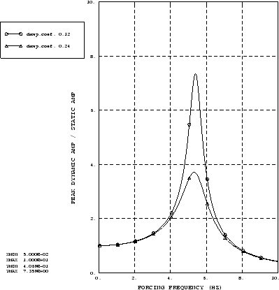
The direct-solution and the subspace-based steady-state dynamic procedures are used to calculate the steady-state vibrations in this system with low and high viscous damping coefficients, 0.12 and 0.24. The dashpot coefficient in this model is defined as a function of the first field variable, and the change of the field variable value is carried out in a dummy general static step placed between two direct-solution steady-state dynamic steps.
Analysis 3 is identical to analysis 2 in all aspects except that hysteretic damping is modeled instead of linear viscous damping. Hysteretic damping, also known as structural or solid damping, is observed in the vibration of many solid materials and can be attributed to internal friction. This form of damping produces a hysteresis loop in the force-displacement plot for each loading cycle that is proportional to the amplitude and tends to stay constant with rising forcing frequency. The energy loss is proportional to the displacement amplitude squared for both viscous damping and for hysteretic damping. This fact suggests that structurally damped systems subjected to harmonic excitation can be modeled as viscously damped systems with an equivalent coefficient of viscous damping that is inversely proportional to the frequency: see Denhartog (1985). The equation of motion for this one-degree-of-freedom system is, thus, written readily as
where is a damping coefficient and is the forcing frequency. The equivalent viscous damping coefficient is For harmonic motion we have the relationship ; therefore, , where is the imaginary number. Hence, the equation of motion can also be written as
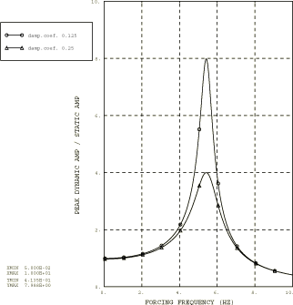
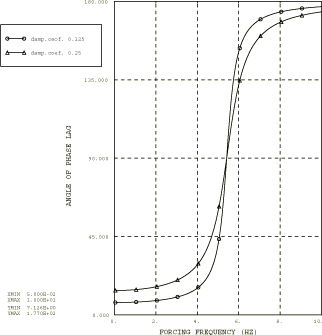
Abaqus also allows direct specification of structural damping; however, this direct specification can be used only in modal-based analysis and is accurate only for small damping values. See Material Damping for further discussion. In this analysis the effects of low damping (=0.125) and high damping (=0.25) are compared, following the same procedure as used in analysis 2. The data set containing the frequency-dependent dashpot coefficients at intervals of 0.05 Hz over the frequency range of 0 to 10 Hz is included (file vibration_dampdata1.inp).
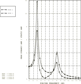
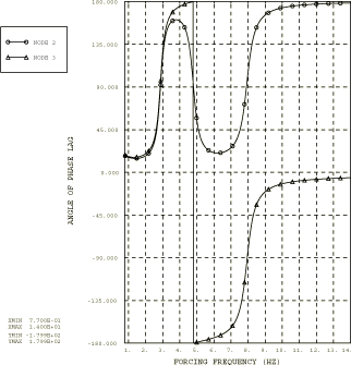
Analysis 4 involves a two-degree-of-freedom system with viscoelastic damping. Viscoelastic materials are often used in a structure to improve the damping characteristics of the structure or its components. In a one-dimensional test specimen made of linear viscoelastic material, an applied cyclic stress will result in a steady-state cyclic strain response, with the same frequency but out of phase by the phase angle . The phase angle is also known as the loss angle and is a function of frequency. The damping ability of the material is dependent on it and not on the stress and strain amplitude. The ratio of the stress and strain defines the complex modulus, , where the real part is termed the storage modulus and the imaginary part the loss modulus. The equation of motion for the steady-state forced vibration of a single-degree-of-freedom viscoelastic system of mass m is simply
where is the complex stiffness proportional to the complex modulus . Making use of the substitution for harmonic motion, we can rewrite the equation of motion as
where and . Referring to Frequency Domain Viscoelasticity, we can identify that the equivalent viscous damping coefficient is and the spring stiffness is , where is the Fourier transform of the nondimensional relaxation function and is the long-term spring stiffness. The equation of motion for viscoelastic damping resembles the one for hysteretic damping to the extent that viscoelastic damping can also be simulated in discrete mass-spring-dashpot systems using frequency-dependent springs and dashpots. This form of damping is simulated in the two-degree-of-freedom discrete mass-spring-dashpot system shown in Figure 1 with the following parameters: and , such that the real and imaginary moduli are , and The frequency dependence of assumes the power law formula , where b is a real constant, is a complex constant, and is the frequency in cycles/time. The equation of motion for the two-degree-of-freedom system is now readily developed and can be written as
Since harmonic loading of the form produces the harmonic oscillation with the complex oscillation amplitude , the equation of motion for the loading parameters used in this analysis, and 0, can be rewritten in terms of the real and imaginary parts of the oscillation amplitudes as follows:
The frequency-dependent spring and dashpot properties are generated by a Fortran program using the basic model constants for the mass, m, and for the spring, In addition, the parameters b=1.38366, =2.3508 × 10⁻², and =6.5001 × 10⁻² are used. This form of the power law dependence of frequency of does not describe the viscoelastic properties for all frequencies accurately. In particular, this formula is incorrect for low frequencies since the stiffness becomes negative. Therefore, values computed using this formula for frequencies below 0.77 Hz are discarded in this analysis. The frequency-dependent data for the dashpot coefficients and for the spring stiffness are written at intervals of 0.035 Hz over the frequency range of 0.77 to 14 Hz.

