Problem description
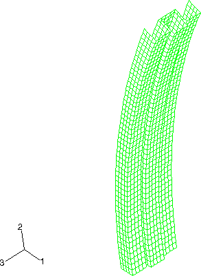
The pillar is composed of two columns of different cross-sections, one box-shaped and the other W-shaped, welded together with spot welds (Figure 1). The top end of the pillar is connected to a rigid body, which makes the deformation of the pillar easy to control by manipulating the rigid body reference node. The box-shaped column is welded to the W-shaped column with five spot welds on either side of the box-shaped column.
The columns are both composed of aluminum-killed steel, which is assumed to satisfy the Ramberg-Osgood relation between true stress and logarithmic strain,
where Young's modulus (E) is 206.8 GPa, the reference stress value (K) is 0.510 GPa, and the work-hardening exponent (n) is 4.76. In the present Abaqus analyses the Ramberg-Osgood relation is approximated using elastic and plastic material properties. The material is assumed to be linear elastic up to a yield stress of 170.0 MPa, and the stress-strain curve beyond the yield stress is defined in piecewise linear segments using plastic material properties. Poisson's ratio is 0.3.
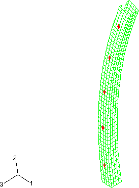
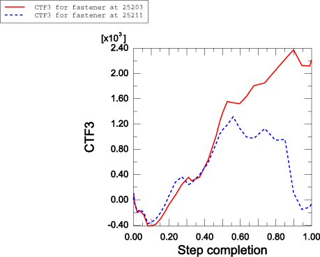
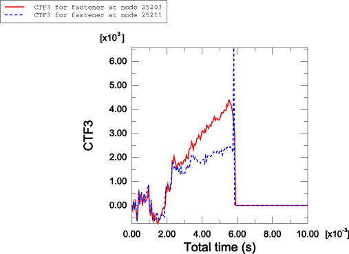
The spot welds are modeled in both Abaqus/Standard and Abaqus/Explicit using the mesh-independent fastener capability. Connector elements with CARTESIAN and CARDAN sections are used to define deformable fasteners. Alternatively, a BUSHING connection type could have been used. The element set containing the connector elements is referenced in the mesh-independent fastener. The spot welds at nodes 5203, 15203, 25203, 35203, and 45203 are all located on the positive z-side of the box-shaped column, with node 5203 at the bottom end of the column and node 45203 at the top end of the column (see Figure 2). Spot welds at nodes 5211, 15211, 25211, 35211, and 45211 are all located on the negative z-side of the box-shaped column, with node 5211 at the bottom end of the column and node 45211 at the top end of the column. The surfaces of the box-shaped column and the W-shaped column are specified in the mesh-independent fastener. The spot welds are defined with a diameter of .002 m. The deformable behavior in the fastener is modeled using connector elasticity, with an elastic spring stiffness of 2 × 10¹¹ N/m in translational as well as rotational components. For the Abaqus/Explicit analysis spot weld damage and failure are modeled using connector damage behavior. A force-based coupled damage initiation criterion that uses a connector potential with both connector force and connector moment ingredients is used. (For further description of the connector potential used, see the spot weld example in Connector Functions for Coupled Behavior.) Damage initiates when the value of the potential exceeds 2 × 10⁵ N. A post-damage-initiation equivalent displacement of 1 × 10⁻⁷ m is allowed. Once the post-damage-initiation equivalent displacement in a spot weld reaches this value, the spot weld ceases to carry any load. Both the continuum and structural coupling capabilities are used to define the fasteners.
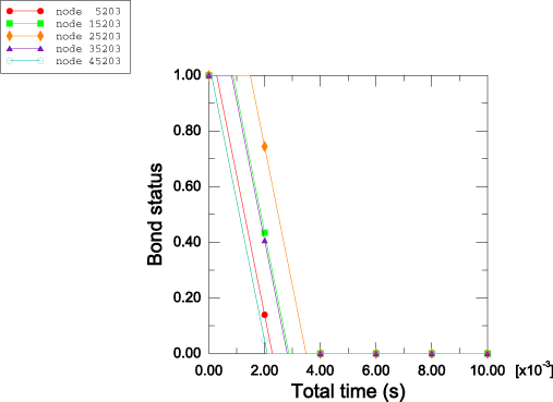
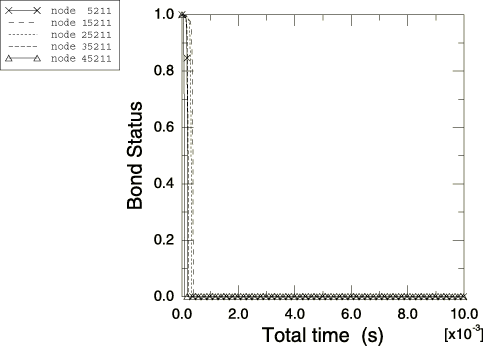
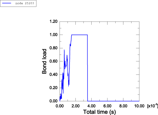
To study spot weld failure and the post-yield behavior of the spot welds in detail, the problem is also solved using the bond properties available in Abaqus/Explicit. The column with the box-shaped cross-section is defined to be the secondary surface in contact with the column with the W-shaped cross-section. The spot welds on the two sides of the box-shaped column are modeled with different yield forces and post-yield behavior to illustrate the two failure models. For the spot-welded nodes 5203, 15203, 25203, 35203, and 45203, the force to cause failure for the spot welds is 3000 N in pure tension and 1800 N in pure shear. Once the spot welds start to fail, the maximum force that they can bear is assumed to decay linearly with time over the course of 2.0 msec, which illustrates the modeling of complete loss of strength over a given time period. For the spot-welded nodes 5211, 15211, 25211, 35211, and 45211, the force to cause failure for these spot welds is 4000 N in pure tension and 2300 N in pure shear. These spot welds fail according to the damaged failure model, which assumes that the maximum forces that the spot welds can carry decay linearly with relative displacement between the welded node and the main surface. The welds are defined to fail completely once their total relative displacement reaches 0.3mm, which illustrates the modeling of loss of strength in the spot welds based on energy absorption.