About Preferences for Connection Display | ||
| ||
Connection Cross-link Management
To create bridges on connections each time a connection crosses another one, select the convenient option from . For more information, see Native Apps Preferences Guide: 2D Graph F/L.
You can customize these cross-link bridges:
| Gap bridges | Arc bridges | Square bridges |
|---|---|---|
 |  |  |

Default Connection Line
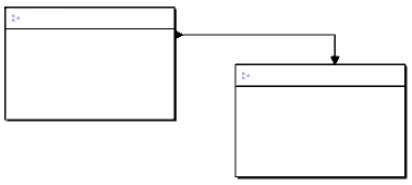
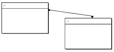
By default, connections are created with an orthogonal line.
To change the default creation mode, select Straight in . For more information, see Native Apps Preferences Guide: 2D Graph F/L.
To change the appearance of your connection line once created, use the context menu. See Modifying Straight or Orthogonal Connection Line.
| Orthogonal Connection Line | Straight Connection Line |
|---|---|
 |  |
Connection Links Display in Tree
If the corresponding options are selected in , connections are displayed in tree in the following categories:
- Connections: The two entities pointed by the connection are present in session.
- Partially Loaded Connections: At least one entity pointed by the connection is not present in session (but both extremities exist).
- Broken Connections: At least one entity pointed by the connection no longer exists.
For more information, see Native Apps Preferences Guide: Tree.