-
From the Function section of the action bar,
click Stiffener on Free Edge
 . .
The Stiffener on Free Edge panel appears.
-
Under Material & Orientation, specify the following
parameters:
-
Select the appropriate material and section for the stiffener.
- Select the required material reference.
- From the
Standard list, select the section standard.
- From the Shape list, select the required section shape.
The
Shape box is unavailable for selection when
the material-section table does not have the
SectionShape column, that is when you are
using the resolved sections.
- From the Size list, select the required section size.
If no Resources
Catalog or Resources Library resource is set in Data Setup, you can click More... to search
and select the material and section references from database. If you select a parametric
section reference from the database, the Size list is updated with
the available sizes and then you can select the required section size.
-
Set the appropriate orientation.
For more information, see Orientation.
If you are unable to find the selected section reference, check the following: - The section reference is available in the database.
- There are no duplicate section references in the database.
- The section reference has the section standard attribute specified in its properties.
-
Under Category & Name, select an appropriate category for
stiffener on free edge from the Category list.
You can change the category while editing the stiffener on free
edge. Note:
If no dictionary
is set in
Data Setup,
only the default category is
available.
- Optional:
Clear the Automatic check box and type the required name in the
Name box.
Note:
If a naming action rule is assigned in
Rules Catalog or Rules Library in Data Setup, and the Automatic check box is
selected, the structural object is named automatically according to the naming action rule.
For more information, see Action Rule for Naming.
-
Select a panel or plate to attach a stiffener on a free edge.
You can select multiple panels or plates on the same support in the
Plate\Panel box.
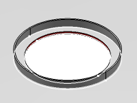
As soon as the panel or plate is selected, its free edges or openings on it are
highlighted in the 3D area.
- Optional:
Select the limit mode.
You cannot change the limit mode once the support is selected.
-
Under Support,
-
In the Support box, select the required edge or
opening.
- Optional:
Click
 and enter
the offset value of the stiffener on free edge from the selected support. and enter
the offset value of the stiffener on free edge from the selected support.
- Optional:
Under Limits, specify the following parameters:
-
Select the start and end limits.
By
default, the labels of the extremities are
Start and
End. However, the labels may change according to the
name of the directions of the bounding box.
-
Specify the offset and normal offset values.
- Optional:
Define the delimitation type.
-
Define the endcut. For more information, see Creating End Cuts.
For more information, see Limits.
-
Under Section Positioning, specify the following
parameters:
-
Specify the required value in the Web Angle box.
By default, the web of a stiffener is placed perpendicular to the panel or
plate.
-
Click Neutral Fibre
 or
Plate Face or
Plate Face
 to define the
position of the anchor point along the direction of the thickness of the panel or
plate. to define the
position of the anchor point along the direction of the thickness of the panel or
plate.
The anchor point is positioned on the face or the neutral fibre of the plate
accordingly.
-
Click OK.
The stiffener on a free edge is created. 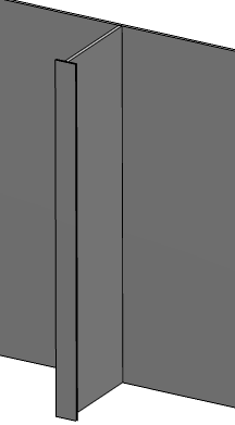 - Optional:
To edit the stiffener of free edge, select the stiffener on free edge in the work area and
click Stiffener on Free Edge
on the context toolbar.
|
 to
manage the multi-selection.
to
manage the multi-selection.