Representation of a Structural Object in 2D
| Unlimited Support |
Panel |
Base support is used for the creation of a panel. Base support can be a plane, a hull surface, or a GSM surface. |
|
Stiffener |
Base support curve used for creation of Stiffener before applying limit. |
|
| Delimited Support |
Panel |
Support after applying the limits to relimit the plate. |
|
Support used for creation of Stiffener |
Support curve after applying the limits. |
|
| View direction | ||
| Primary object | ||
| Secondary object | ||
Panel
|
Panel Type |
Description |
Result in 2D |
View Type |
|---|---|---|---|
|
Primary Panel |
Panels that are parallel to the view plane (within the angular tolerance of the primary objects) are considered as primary objects. |
Result is projection. |
Top view |
|
Panel Limited to Primary Object |
Below secondary object tolerance: Panels that are orthogonal to the primary objects (within the angular tolerance of the secondary object). |
Result specified in the structural view panel for below tolerance. |
Side view |
|
Above secondary object tolerance: Panels that are not orthogonal to the primary objects (above the angular tolerance of the secondary object). |
Result specified in the structural view panel for above tolerance. |
Any view |
|
|
Crossing Panel |
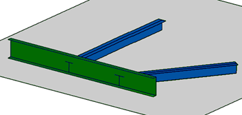
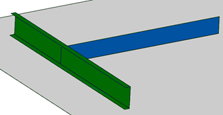
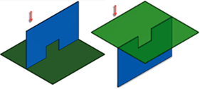
If a panel is passing through a primary object (primary panel is limited to secondary panel) as shown in the figure crossing panel in 3D, then the panel is considered as crossing panel |
Cut by primary unlimited support. |
Side view |
|
Cut by primary delimited support. (If the crossing panel has more than one primary object and all these primary objects are not in the same plane.) |
|||
|
Shell Panel |
All the shell panels and its sub category are process separately. |
Cut by primary unlimited support. |
Side view |
|
Cut by primary delimited support. (If a shell panel is connected to more than one primary object and all these primary objects are not on the same support plane or one of the primary panels is a knuckled panel.) |
- Panel Limited to Primary Object
- Representation of the secondary object plane based on the result type is as shown below:
- Symbolic: Symbolic Representation of the Panel
-
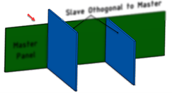
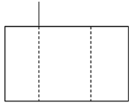
Configuration SFD SDD Perpendicular to primary object.
A symbolic line at the position of the secondary panel.
A symbolic line at the position of the delimited support of the secondary panel.

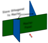
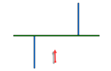
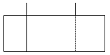

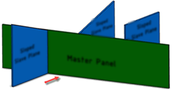
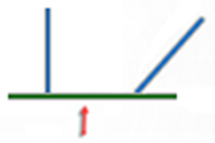
Sloped secondary panel.
Panels that are not orthogonal to the primary object.
A symbolic line at the intersection between the secondary panel and the primary panel.
A symbolic line at the intersection between the delimited support of the secondary panel and the support of the primary panel.

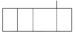

Panel with opening on the boundary.
Note: As delimited support does have any opening, the result in 2D with symbolic representation is without any opening.
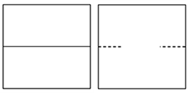
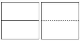
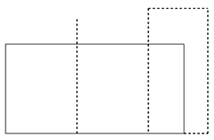
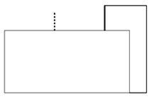
- Projection: Mechanical Projection of the Panel
-
Configuration SFD SDD All secondary panels Mechanical projection of the panel Mechanical projection of the panel 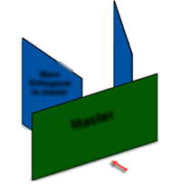
- Cut by Primary
-
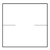
Configuration SFD SDD All secondary panels Intersection of the secondary panel with the primary delimited support.
Result is single line.
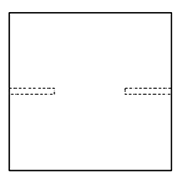
Intersection of secondary solid panel with the primary delimited support.
Result is double line.
If the primary delimited support touches only one face of the secondary panel, the result is a single line.
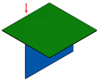
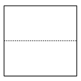
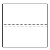
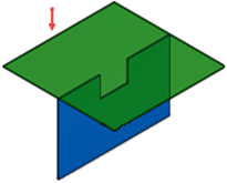
- Cut by View Plane
-
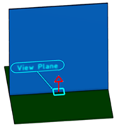
Configuration SFD SDD All secondary panels Intersection of secondary panel with the view plane.
Result is a single line.
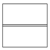
Intersection of secondary solid panel with the view plane.
Result is a double line.

 Notes:
- To get the correct result, the view plane must intersect with the secondary plane.
- If the intersection of the secondary panel and the view plane is behind another structure object along the view looking direction, the part of the panel that is hidden is considered as a hidden part. It is not drawn in 2D unless the hidden line option is activated.
- Crossing Panels
-
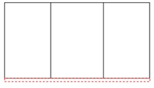
Configuration SFD SDD Panel is passing through the primary object (primary panel is limited to secondary panel.)
Intersection of secondary panel with the primary unlimited support.
Result is single line.
Intersection of secondary solid panel with the primary unlimited support.
Result is double line.
If the primary unlimited is a surface support that touches only one face of the secondary panel, the result is a single line.

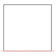
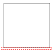
Crossing panel has more than one primary object that is in different planes. Intersection of the secondary panel with the primary delimited support.
Result is single line.
Intersection of secondary solid panel with the primary delimited support.
Result is double line.
If the primary delimited support touches only one face of the secondary panel, the result is a single line.
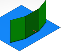
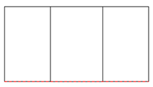
- Shell Panels
-
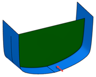
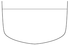
Configuration SFD SDD Shell panel with one primary object. Intersection of secondary panel with the primary unlimited support.
Result is single line.
Intersection of secondary object solid panel with the primary unlimited support.
Result is double line.
If primary unlimited is a surface support that touches only one face of the secondary panel, the result is a single line.


Shell panel connected to more than one primary object.
Intersection of secondary panel with the primary unlimited support
Result is single line.
Intersection of secondary solid panel with the primary unlimited support.
Result is double line.
If the primary unlimited is a surface support that touches only one face of the secondary panel, the result is a single line.
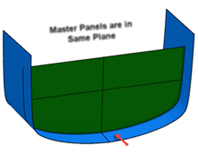
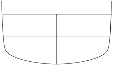
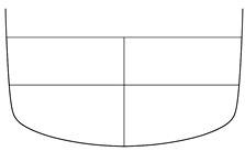

Shell panel connected to more than one primary objects that are in different planes. Intersection of secondary panel with the primary delimited support
Result is single line.
Intersection of secondary solid panel with the primary delimited support
Result is double line.
If the primary delimited is a surface support touches only one face of the secondary panel, the result is a single line.
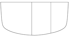
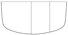


- Representation of Cut by Primary Delimited Support in SDD Based on the How the Primary Delimited Support Intersects with the Secondary Panel
-
Delimited support touches both face of the secondary panel Representation of Cut by primary delimited support (Result is double line) Delimited support touches only one face of the secondary panel Representation of Cut by primary delimited support (Result is single line) 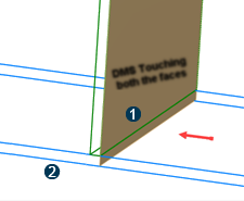
 - Delimited support
 -
Secondary panel
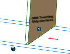
 - Delimited support
 -
Secondary panel
Crossing Stiffeners
|
Stiffener type |
Description |
Result type |
View type |
|
|---|---|---|---|---|
|
Stiffeners on side view |
Stiffeners on the side view (Stiffener web is parallel to the view plane) are considered as primary objects |
Symbolic |
Side view |
|
|
Stiffeners limited to primary object |
Stiffener below tolerance | Stiffeners that are orthogonal to the primary object along the stiffener trace (or slope is below the angular tolerance of the secondary object.) |
Result specified in the structural view panel for below tolerance |
End view |
| Stiffener above tolerance | Stiffeners that are not orthogonal to the primary object along the stiffener trace (slope is above the angular tolerance of the secondary object.) |
Result specified in the structural view panel for above tolerance. |
Any view |
|
|
Stiffeners passing through the primary object |
All stiffeners passing through the primary object are processed separately. |
Cut by primary object. |
End view |
|
- Representation of Stiffener on Side View
-
Configuration SFD SDD Stiffener on side view
Web view of the stiffener
Web view of the stiffener

Far side 

Near side 

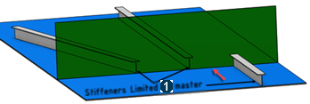
- Limited to Primary Objects
- Symbolic
-
Configuration SFD SDD Stiffener on end view
 -
Stiffeners limited to primary object
-
Stiffeners limited to primary objectPosition of stiffener section end 
Position of stiffener section end 
- Projection: Mechanical projection of stiffener
-
Configuration SFD SDD All secondary stiffeners
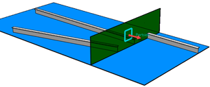
Mechanical projection of stiffener 
Mechanical projection of stiffener 
- Cut by Primary
-
Configuration SFD SDD All secondary stiffeners that intersect with the primary object

 -
Stiffeners limited to primary object
-
Stiffeners limited to primary objectIntersection of stiffener section with the primary unlimited support. 
Intersection of solid stiffener section with the primary unlimited support. 
- Cut By View Plane
-
Configuration SFD SDD All secondary stiffeners that intersect with the view plane

 -
Stiffeners limited to primary object
 - View
plane
- View
planeIntersection of stiffener section with the view plane 
Intersection of solid stiffener section with the view plane 
- Stiffener Passing Through Primary Object
-
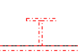
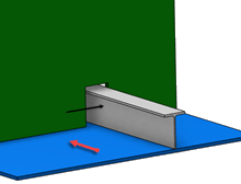
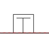
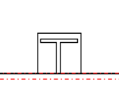
Configuration SFD SDD Stiffener passing through primary object
Intersection of stiffener section with the primary unlimited support Intersection of solid stiffener section with the primary unlimited support 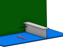

Welded Stiffeners
| Stiffener Type | Description | Result Type | View Type |
|---|---|---|---|
| Welded Stiffeners | Stiffeners that are attached to primary panels are considered as welded stiffeners. | Symbolic weld, Projection | Top view |
| Result Type | SFD | SDD |
|---|---|---|
|
Symbolic Weld |
Result is a single line that is along the stiffener trace. |
Result is a single line that is along the stiffener trace. |

|
 |
 |
|
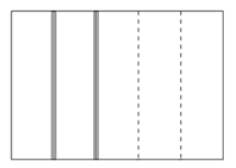
Projection |
Mechanical projection of the stiffener. |
Mechanical projection of the stiffener. |

|
 |
 |
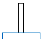
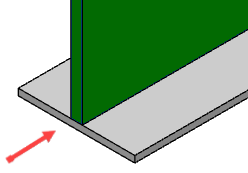
Stiffener on Free Edge
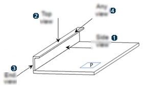
Default representation of the stiffener on a free edge is based on the view direction.
|
Looking Direction |
Description |
Result Type |
View Type |
|
|---|---|---|---|---|
|
Side View |
Web face is parallel to the view plane (or the angle between weld and view plane is below the angular tolerance of the primary object.) |
Projection |
Side View |
|
|
Top View |
Flange is parallel to the view plane (or the angle between flange and view plane is below the angular tolerance of the primary object.) |
Projection |
Top View |
|
|
End View |
If stiffener on free edge is passing through to view plane. |
Cut By View Plane |
End View |
|
|
Otherwise |
Symbolic |
|||
|
Any view |
Neither the weld nor the flange is parallel to the view plane. |
Projection |
Any View |
| View Side | SFD | SDD | ||
|---|---|---|---|---|
| Top View | 
|
 |

|
 |
| Side View | 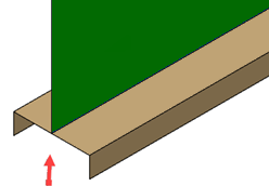 |
 |
 |
 |
| End View | 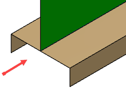 |
 |
 |
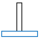 |
Pillars
Representation of pillars or beams is based on the view side.
Pillars that are perpendicular to the primary object along the pillar length (within the angular tolerance of the secondary object) are considered as the end view. Or else, they are considered as side view.
- End View Representation of Pillar
-
Configuration
Pillar in 3D
Pillar in 2D
Pillar on Near Side
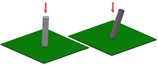

Pillar on Far Side

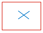
Pillar on Both Side
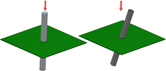

For more information on pillar representation, GVS, view side, color, and symbol for pillars or beams, see 3D Modeling: Multi Discipline Engineering: Structure Functional Design: Administration: Working with Drawing Production: Graphic Replacement for Beams.
- Side View Representation of Pillar
-
Pillar on Side View in 3D
Symbolic Representation of Pillar
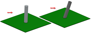
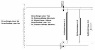
Depending on the GVS parameters for the side view of the beam, the result is Symbolic or Projection. For more information, see 3D Modeling: Multi Discipline Engineering: Structure Functional Design: Administration: Working with Drawing Production: Graphic Replacement for Beams.
