Creating a Structural View | |||||
|
| ||||
- From the Smart View section of the action bar, click Create Structural View
 .
. -
In the Smart View Panel dialog box, click
Selection
 and select a 3D
object from the 3D area.
Recommendation: Select a 3D product containing either Structure Functional Design (SFD) parts or Structure Design (SDD) parts. Do not select a product having both the SFD and SDD parts, or you may not get the expected result.
and select a 3D
object from the 3D area.
Recommendation: Select a 3D product containing either Structure Functional Design (SFD) parts or Structure Design (SDD) parts. Do not select a product having both the SFD and SDD parts, or you may not get the expected result. -
Select a view template from the following:
- View Items: You can directly reuse a view template from another view.
- View Templates: You can select a view template from the
Catalog Browser
 .
.
The template chapter is saved as preference for next time usage.Tip: In the Catalog Browser , you can
double-click a template to select it.
-
Select a plane from the tree, or from the 3D area, or from the project plane systems.
Notes:
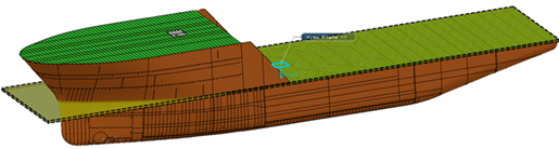
- A structural box is created along the selected view plane up to the part end.
- If you change the plane selection during structural view creation, the default structural view box is recomputed.
-
Click Show Structural View Specification
and
modify the following structural parameters:
You can hide or show Structural View Specification dialog box by clicking
. - Edit the angular tolerance of the primary object.
Angular tolerance for primary object value must be 0–45 deg. During view update, the angle is computed between the panel normal and the view direction. If the angle is within the angular tolerance, it is considered as a primary object.
Show Primary Object Panels: You can see the list of primary objects computed with the box and angular tolerance.
- Edit the angular tolerance of the secondary object.
By default, the Same as primary check box is selected. If you modify the primary object angular tolerance, the angular tolerance value of the secondary object is also updated.
Note: Clear the check box to manually update the angular tolerance value of the secondary object (0–45 deg). - Under Default Secondary Object Representation, edit the default result for the structural secondary object.
- Under Default Structural Box, click
Edit
 to edit
the near and far offset parameters.
to edit
the near and far offset parameters. - Select the Filter Isolated Parts check box to filter out all the isolated parts.
- Select the Filter only Isolated parts not crossing any primary object or View plane check box to filter only isolated parts that do not cross the primary object or the view plane.
- Select the Enable Selective Filter check box to enable the filter based on the type of structure object.
- Click Add to add a structure type to the filter
list. Note: Clear the Enable Selective Filter check box to remove all the added structure object types from the list.
- Edit the angular tolerance of the primary object.
-
Click
OK to generate the structural view in the
sheet.
Notes:
- The default result for the panels that are crossing the primary object are cut by the view plane. By default, all crossing panels are cut by the primary object and all edge stiffener of the category face plate are projected.
- You can change the result using the change object command after view creation. For more information, see Modifying the 2D Result Corresponding to a Structural Object.
- All the structural objects that are not connected to the primary object projected or cut
by the view plane if intersects, the default value for primary and
secondary specification such as angular tolerance, or the default
structural box offset, then the default secondary object
representation values are retrieved from Me
 > Preferences.