Defining Forced Values | ||||||
|
| |||||
- Select a scenario in the tree.
-
From the Scenario section of the action bar, click Edit probes and
excitations
 .
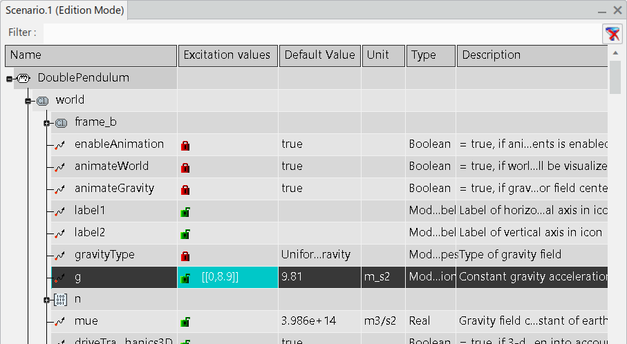
The Scenario window appears and displays the model structure, from the functional or logical component to the dynamic behavior.
 -
Expand a behavior and right-click an input or an output, and select Edit
time table.
The Edit Forced Values dialog box appears to let you modify one or more variables.
Tip: To edit just one variable at a time, you have two possibilities: - Right-click the variable under the Forced Values node in the tree and select Object > Definition.
- Select the variable under the Forced Values node in the tree and click Edit > Properties.
-
Enter, modify or remove a value in the Edit Forced Values dialog
box.
Tip: The format of the value is a table with dimension 2xn with a Modelica format: [[t1, x1] [t2, x2]...[tn, xn]] or [[t1, x1];[t2, x2] ;... ;[tn, xn]].
t is the time when the value x is forced
t must be positive
If the t values are not ordered, the table is automatically reordered.
- Optional:
To paste forced values from clipboard:
-
Select Paste from clipboard.
To create supported data in the clipboard you can:
- Copy a table from Microsoft Excel with as many columns as variables (including time).
- Right-click a curve (with time as X axis) in a plot and select Copy to clipboard > Copy curve.Notes:
- You can copy a simulation result from a watchlist this way.
- Copy to clipboard > Copy point does not generate supported data.
The forced values appears in the Edit Forced Values dialog box. - Click OK to validate your modification.
-
Select Paste from clipboard.
- Optional:
To import forced values from a CSV file:
-
Select Import.
The Import Time Table dialog box appears.
-
Browse and select the convenient CSV file then click
Open.
The forced values appears in the Edit Forced Values dialog box.
- Click OK to validate your modification.
-
Select Import.
- Optional:
To export forced values in a CSV file:
-
Select Export.
The Export Time Table dialog box appears.
-
Browse and select the convenient folder to export your CSV file then click
Save.
The forced values are exported in a CSV file.
-
Select Export.
-
Click OK to validate your modification.
- The forced value is displayed in the Scenario window.

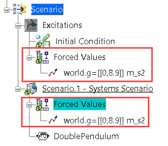
- In the tree, a Forced Values node
appears in the following locations:

- In the Scenario category.
- In the Excitations category, to allow you to share the forced value excitation with other scenarios. For more information about sharing excitations, see Sharing Excitations and Probes Between Scenarios.
Note: To display values for parameters in the tree, you must activate the Display values in the specification tree preference from Me > Preferences > App Preferences > 3D Modeling
> Multi Discipline Automated Engineering > Basics, the Parameters & Relations tab, the
Parameters tree view group.
- The forced value is displayed in the Scenario window.
-
To delete a forced value, remove the corresponding text in the
Scenario window.
Important: If you change or delete a forced value, it is also changed or deleted in all other scenarios where it is used. To create an excitations that is not shared, you have to copy it. For more information about copying excitations, see Copying and Pasting Excitations and Probes between Scenarios.