Graphic Replacement for Stiffener on Free Edge | ||||
|
| |||
You can customize generative view style parameters for stiffener on free edge. These parameters are shared by all structure apps. Customizing parameters in this file affects the appearance of your drawings and is an administrator's task.
| Important:
The system internally differentiates the stiffener on free edge as face plate and stiffener on free edge. The face plates are drawn as mechanical projection, whereas the stiffeners on the free edges are drawn similar to the stiffeners. While generating a logical view, in EndView, the section of the face plate is projected instead of a mechanical projection. |
For the sample GVS files, see 3DEXPERIENCE Native Apps Content Reference Guide: Samples for Drafting.
Sample XML File
In the sample XML file, generative view style parameters for stiffener on free edge are located towards the bottom of the file under StructureObjects.
StiffenerOnFreeEdge
- Draw
- Graphic Replacement
- ViewType
- SpecifyViewType
Lets you specify the view type.
- TopView
- ResultType
- NearSide
- FarSide
- AccrossSide
- AnnotationTextStyle
- FlangeOrientationSymbol
- ExtremitySymbol
- MaterialExtrusionSymbol
- SideView
- ResultType
- NearSide
- FarSide
- AccrossSide
- AnnotationTextStyle
- FlangeOrientationSymbol
- ExtremitySymbol
- SlotContour
- EndView
- AnyView
- SpecifyViewType
- Draw
- Specifies whether to draw the stiffener on free edge.
- GraphicReplacement
- Indicates whether to use graphic replacement. Yes or No.
- ViewType
- There are four view types for stiffeners: TopView, SideView, EndView and AnyView.
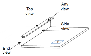
Each has NearSide, FarSide and AcrossSide parameters and AnnotationTextStyle parameters.
Additionally, TopView has:
The SideView also has FlangeOrientationSymbol and ExtremitySymbol parameters. The FlangeOrientationSymbol parameters for the SideView are different than the one for TopView view.
Note: Logical and Functional Tolerance and Annotation (FTA) Section are the only modes, where you can compute AcrossSide parameters, which are similar to NearSide and FarSide parameters. The default values are same as NearSide values. If you are not interested in an AcrossSide analysis, you need to synchronize Near and Across Linetype and LineThickness.
- FlangeOrientationSymbol for Top View
- Draw
- To draw a flange orientation symbol at the ends of a stiffener. Default is Yes.
- ChapterName
- The name of the chapter containing FlangeOrientation symbols within the Drawing Symbol Structure Catalog.
- SymbolName
- The symbol name to draw.
- ReferenceScale
- Scale factor to apply to the symbol as drawn. Default is 1.
- SymbolLocation
- The location on the line representation of the plate where the throw orientation will be drawn. Values are:
1 = Start
2 = Middle
3 = End
The following figure shows a stiffener in TopView FarSide with a SymbolLocation of Start.
The following shows a stiffener in TopView FarSide with a SymbolLocation of Middle.
- ExtremitySymbol
- Draw
- Indicate Yes to draw arrowheads at the extremities. No is the default (arrowheads are not drawn.)
- MinimumLengthRatio
- A percentage of the length of the stiffener used to determine if there is enough room to draw the extremity symbols without overlap. The default is 45. In other words, the length of the symbol placed at an extremity may not exceed 45% of the total length of the stiffener, taking into account the ReferenceScale and the view scale.
- ReferenceScale
- Scale factor to apply to the symbol as drawn. Default is 1. (A value of 2 results in a placed symbol twice as big.)
- ChapterName
- The name of the chapter containing extremity symbols within the Drawing Symbol Structure Catalog.
- DefaultExtremitySymbol
- The default symbol used to represent the end of a stiffener without end cuts.
- ExtremitySymbolByEndCutType
- Draw
- Indicates stiffener end symbol is dependent on the end cut type (Yes). No (default) indicates the SymbolsAtEndsOfProfile option will always be used.
- Snipe
- The symbol used for a Snipe end cut.
- Weld
- The symbol used for a Weld end cut.
- Trim
- The symbol used for a Trim end cut.
The following shows a split stiffener in TopView with an ExtremitySymbolByEndCutType of Snipe and Trim end cuts.

The following shows a split stiffener in SideView with an ExtremitySymbolByEndCutType of Snipe and Trim end cuts.
- MaterialExtrusionSymbol
- Draw
- Draws the material throw orientation. Yes or No.
- MaterialExtrusionMode
- Draws the material throw orientation. Values are:
1 = Tick mark (true width)
2 = Throw orientation (symbolic)

3 = Tick mark and throw orientation

- SymbolLocation
- The location on the line representation of the plate where the throw orientation will be drawn. Values are:
1 = Start
2 = Middle
3 = End
- MaterialThroughOrientationSymbol
- ChapterName
- The name of the chapter containing material through orientation symbols within the Drawing Symbol Structure Catalog.
- SymbolName
- The symbol name to draw.
- ReferenceScale
- Scale factor to apply to the symbol as drawn. Default is 1.
- TickMarkSymbol
- Length of tick mark when drawing a tick mark. Default is 5.0 millimeters.
- FlangeOrientationSymbol for Side View
- Draw
- Draws the flange orientation symbol on the stiffener representation. By default, it is Yes.
- OffsetMode
- The mode by which the offest will be applied. By default, the offset mode is Absolute.
- OffsetValue
- The value by which an offset is applied to the flange. OffsetValue is a real length. By default, the offset value is 50.
Here is the example of the L-section stiffener:
NearSide 
FarSide