Introduction to Multibody System Simulations using the 3DEXPERIENCE Platform | ||
| ||
Mechanisms
A mechanism is an assembly of bodies moving relative to each other and according to predefined constraints. A mechanism includes specific elements (for example, bodies, joints, markers, and motion drivers) and unique mechanism features (for example, gravity). For more information, see About Mechanisms.
Bodies are the elements to which you can assign mass properties. The bodies themselves can be rigid or rigid massless. For more information, see About Bodies.
The bodies are connected to each other or to a global reference system by means of joints. The joints determine how the different bodies can move with respect to each other. The joint degrees of freedom are represented by a number of state variables that define the motion of the body. For more information, see About Joints.
Markers are local coordinate systems associated with a body and used as coordinate reference to define joints, applied forces, and other elements. For more information, see About Markers.
Workflow Overview
A 3DEXPERIENCE multibody system simulation typically consists of the following steps:
- Create the design of the mechanical system.
- Create parts defining the geometric shape, (for example, using the Part Design app).
- Organize the parts into products (subassemblies, which may contain multiple parts) to assemble the complete mechanical system (for example, using the Assembly Design app), including engineering connections between the parts.
- Open the model in Motion Analysis.
- Decide how to model your real system as a set of connected elements by selecting the
products and engineering connections to be included in your mechanism.
Each product is mapped to a body, engineering connections are mapped to joints, and the product structure axis systems are mapped to markers.
For more information, see Creating Mechanisms, Creating Bodies, Creating Joints, and Creating Markers.
- Add motion-specific elements (for example, contact interactions) or machine elements (for example, helical or torsional springs and elastic mounts). For more information, see Creating 3D Contacts, Machine Elements.
- Apply an excitation to a body using motion drivers (a driver specifies the motion of
specific mechanism elements through time using functions) or applied forces.
You can control the motion of each degree of freedom of any joint by assigning customized functions on the motion drivers. For more information, see Creating Joint Drivers, Creating Functions.
You also can define force and torque excitations using functions. For more information, see Applying Loads. External loads influence the motion of the system within its degrees of freedom.
- Specify the analysis case and the associated mechanism.
- Run a kinematic analysis (for example, to verify the position, velocity, acceleration of the bodies) or a dynamic analysis (for example, to verify the mass of the bodies or forces of your system).
- Review the animation of your model, as well as 2D plots of the analysis results.
Example Use Cases
Motion Analysis supports many use cases for general machinery applications (usually with complex geometries) comprised of rigid bodies that might include contact interaction, springs, and bushings, with joints connecting the bodies. The models are often fully parametrized product structures with predefined parts and engineering connections that convert automatically into bodies and joints. The applications include basic multibody system and do not consider advanced application-specific elements, such as tires, gear drives, or chain systems.
. For these cases, you can use Motion Analysis to animate the kinematic or dynamic behavior of your system; to plot the position, velocity, acceleration of the bodies; and to study the forces acting in the drivers, joints, and machine elements or in a contact area.
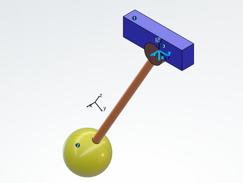
In the following example, a revolute joint is created automatically from engineering
connections and existing axis systems; the pendulum is rotating around the z-axis of the
highlighted axis system (![]() ). You can use Motion Analysis, for example, to add a force on the mechanical system and to study the impact of the
force on the pendulum's free motion.
). You can use Motion Analysis, for example, to add a force on the mechanical system and to study the impact of the
force on the pendulum's free motion.

| Fixed support (body 1) | |
| Pendulum (body 2) | |
| Axis system (marker) |
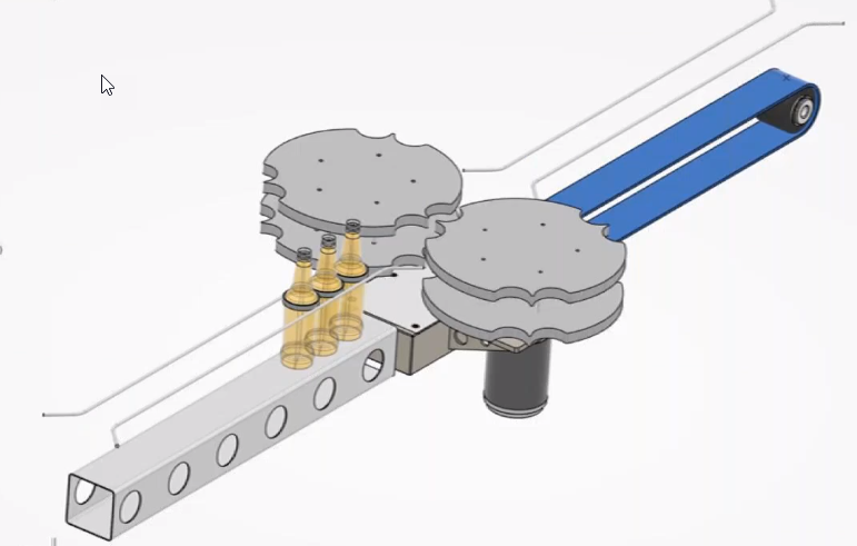
The following figure shows an example of a bottling line, where the contact between the bottles and the starwheels is studied.

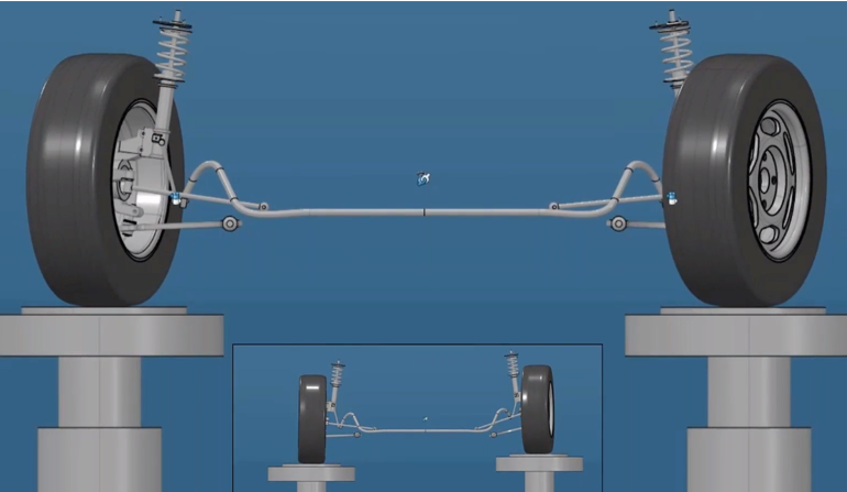
Another typical application is the study of elasto-kinematics for vehicle suspension:
