What's New | ||
| ||
R2022x FD01 (FP.2205)
- You can now upgrade simulation objects created in Motion Design and xMotion Design for use in Motion Analysis.
- You can create knowledge parameters for mechanism and scenario elements and use them to create knowledge formulas, design tables, or knowledge rules.
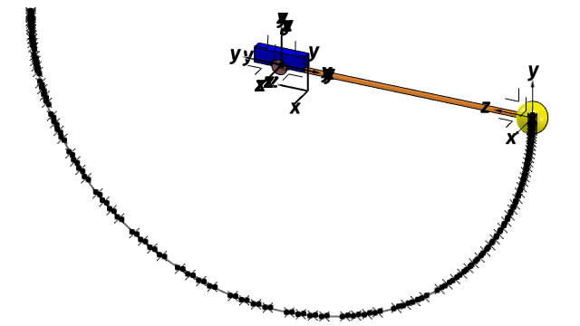
- You can generate the geometric trace of a point, vertex, edge, or curve to visualize its motion during the mechanism simulation.
- You can use geometric elements to define the origin, position, and orientation of a marker.
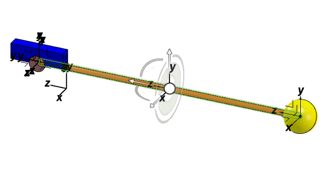
- You can create screw joints in a mechanism to translate and rotate two bodies around the same axis.
- You can update the weight information of a body based on the weight of its associated geometry.
- You can select a mechanism element in the tree or 3D area to highlight the element and all its referenced objects in the tree and in the 3D area.
- You can define the settings of a mechanism to specify the options and initial states to consider during the computation of the mechanism.
Compatibility Between Motion Apps
Benefits: Upgrading mechanisms and simulation objects created in Motion Design and xMotion Design allows you to access the more advanced motion simulation capabilities in Motion Analysis.
For more information, see
About Model Compatibility Between Apps
Creating Knowledge Parameters
Benefits: Knowledge parameters and formula let you visualize and define the
relations between mechanism and scenario elements (states, output values,
associated elements).
For more information, see 3D Modeling | Multi Discipline Automated Engineering | Knowledge Basics | Managing Relations | Formulas | Creating a Formula.
Generating Geometric Traces of Body Elements
Benefits: You can anticipate and visualize the motion of specific body elements
during a simulation before computing the mechanism.
For more information, see
Generating Geometric Traces
Creating Markers Using Specific Geometric Elements
Benefits: You can define markers more easily using specific elements of a
geometry.
For more information, see
Creating Markers
Creating Screw Joints
Benefits: You can create mechanical relations inside a mechanism adapted to your
model.
For more information, see
Creating Screw Joints
Updating the Weight of Bodies
Benefits: You can easily compute and update the weight information of a multibody
system before running a dynamics simulation.
For more information, see
Updating the Weight of Bodies
Cross-Highlighting Mechanism Elements
Benefits: You can better visualize the internal and external elements referenced
by the different mechanism elements.
For more information, see
Element Visualization
Setting Mechanism Preferences
Benefits: You can define specific settings to improve the performance of the
simulation.
For more information, see
Setting Mechanism Preferences

