Creating Conical Bends | |||||||||
|
| ||||||||
-
From the
Model section of the
action bar,
click
Conical Bend
 .
.
-
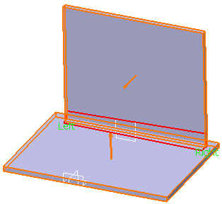
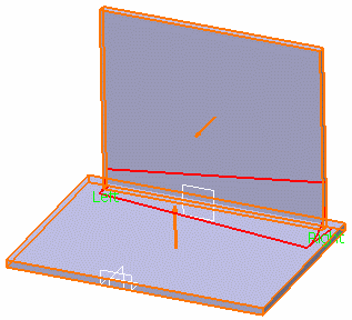
Select the first wall as
Support 1 and the second wall as
Support 2.
The left and right endpoints are identified. You can click the arrows on the geometry to invert the walls orientation.

-
Enter the radius values for each end of the conical bend.
The Angle box is locked. If you click Preview, the value is updated, indicating the angle value between the two walls between which the bend is computed.

Important: - By default, the right radius amounts to twice the left radius.
- The radius is computed based on the left and right endpoints for the bend. This radius, once computed, will be larger than the specified value.
- When the size of each support differs, the bend may exceed the top of the cone. In this case, computing the radius value is impossible.
- Optional:
Select the unfold method, and specify its parameters:
Option Description K-factor Defines the neutral fiber position inside the thickness, from the inner side of the bend. Bend Allowance The bend allowance corresponds to the unfolded bend width. Bend Deduction The bend deduction represents the sheet metal deformation when the bend is unfolded. - Optional:
Select one of the following for each bend extremity:
If you create a feature on the extruded profile, the bend extremities may be recomputed to ensure a consistent result.
Option Description Minimum with no relief The bend corresponds to the common area of the supporting walls along the bend axis, and shows no relief. Square relief The bend corresponds to the common area of the supporting walls along the bend axis, and a square relief is added to the bend extremity. The Length 1 and Length 2 parameters can be modified if needed. Round relief The bend corresponds to the common area of the supporting walls along the bend axis, and a round relief is added to the bend extremity. The Length 1 and Length 2 parameters can be modified if required. Linear The unfolded bend is split by two planes going through the corresponding limit points (obtained by projection of the bend axis onto the edges of the supporting walls). Tangent The edges of the bend are tangent to the edges of the supporting walls. Maximum The bend is calculated between the furthest opposite edges of the supporting walls. Closed The bend corresponds to the intersection between the bends of the two supporting walls. The closed bend extremity lies on the surface of the encountered bend. Flat joint The two bends are joined in flat view.