Creating Bends from a Line | ||||||||
|
| |||||||
-
From the
Model section of the
action bar,
click
Bend From Flat
 .
.
-
In the
Profile box, select a profile containing the
lines.
The selected lines appear in the Line list and the fixed point is automatically set on the face where the profile lies. It represents part of the wall that does not move during the bend creation.
Note: You can clear Use the same parameters for all bend lines to apply different parameters to each fold created from sketch lines. -
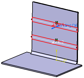
Choose the line type for the profile:
Option Description  Axis
AxisThe line defines the rotation axis of the mobile wall, (that is the bend is symmetrical to the line).  BTL Base
Feature
BTL Base
FeatureBTL: Bent Tangent LineThe line lies on the wall and corresponds to the limits of the bend's fillet.  IML
IMLIML: Inner Mold LineThe line is created by intersecting the internal surfaces of the bend before filleting and the wall.  OML
OMLOML: Outer Mold LineThe line is created by intersecting the bend support and a plane perpendicular to the wall and normal to the OML.  BTL Support
The line lies on the bend support and corresponds to the limits of the bend's fillet. Notes:- You cannot create a bend from flat if the bend length is null in the unfolded view. A warning message appears indicating the values that you need to modify.
- You can click
Reverse
 to invert the bending direction.
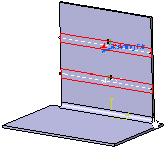
-
Select another fixed point as shown below.
The fixed point must lie on a face containing the profile.
-
Click OK.